Slave to the Game
Online Gaming Community
ALL WORLD WARS
T-34 TANK SERVICE MANUAL

THE DIRECTORATE OF THE ARMOURED FORCES OF THE RED ARMY
For Service Use.
T-34 TANK
SERVICE MANUAL
People's Commissariat of Defence
of the U. S. S. R.
Moscow 1942
Chapter I. SHORT DESCRIPTION OF THE TANK
The T-34 is a tracked fighting vehicle. The crew of tank consists of four men. The Tank is armed with a 76 mm. tank gun and two machine guns. The principle parts of the tank are:
1. Hull and turret
2. Armament
3. Engine
4. Transmission
5. Suspension
6. Equipment
The Hull
The hull is divided into four compartments, driving, fighting, engine and transmission.
The driving compartment is situated in the front part of the tank; it contains the seats of the mechanic-driver and gunner-wireless operator, the driving controls, instruments, engine controls and electrical equipment, machine gun, part of the fighting equipment. wireless set (not in all tanks) , three periscopes, control for rear louvres, two compressed air bottles, spare parts, tools and ancillaries.
The driver's hatch is in the glacis plate. In the floor at the feet of the gunner-wireless operator, there is an auxiliary escape hatch which is closed by an armoured door from within. The driver's hatch is fixed with hinges and has two locks which can be opened from within by pulling a strap which connects both locks. To assist opening the hatch a balancing mechanism (Plate I) is provided together with a catch and handwheel for supporting it in the open position.
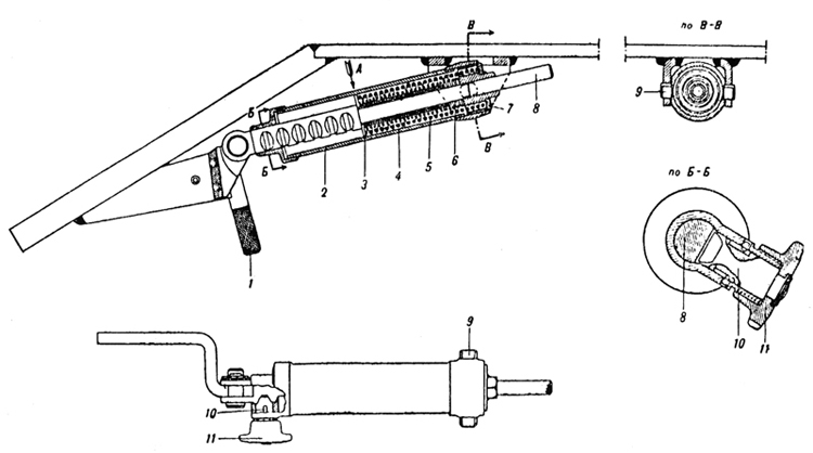
Plate 1 - Balancing mechanism of the driver's hatch
1. Hand lever
2. Body
3. Plate
4. Spring
5. Centralising bush
6. Spring
7. Rear flange
8. Rod
9. Pivot
10. Lock
11. Handwheel
The fighting compartment is situated in the middle part of the tank. It contains the seats of' the tank commander and the turret gunner. The turret which rests on a ball race on top of the fighting compartment contains the 76 mm. tank gun and the ATmachine gun co-axially mounted, part of the fighting compartment and observation instruments.
Behind the removable plate of the partition are four fuel tanks - two at each side. In the middle and at the sides, part ,of the fighting equipment is kept. In the right hand corner there is an electric fan. On the roof of the fighting Compartment there arc six openings -three at each side. The central openings are used for filling up the tanks with fuel; and the remainder are for inspection, maintenance and lubrication of the suspension. In the floor of the fighting compartment there are three openings under the fuel tanks for draining off fuel ( the openings are closed by threaded plugs). There are also four slits for the removal and inspection of the suspension units. These are closed by caps on the outside of the tank.
The Engine compartment is situated behind the fighting compartment and is separated from it by a dividing bulkhead (Plate 2). The following are installed in the engine compartment: the engine, two water cooling radiators, two oil tank , radiators, four accumulators. The floor of the engine compartment is fitted with an access door for the oil pump and water pump ( this is closed by an armoured cover on the outside of the vehicle), an aperture for draining water and three slits for the removal and inspection of the suspension (these slits are closed by means of armoured covers on the exterior of the vehicle).
The engine compartment roof has a large hatch for access to the engine (this is closed by a cover and secured by a lock), two air louvers over the radiators. There are four access plates at each side; the central ones provide access to the filler plugs and oil tank cocks and the ones at each side are for access to the adjustment of the suspension.
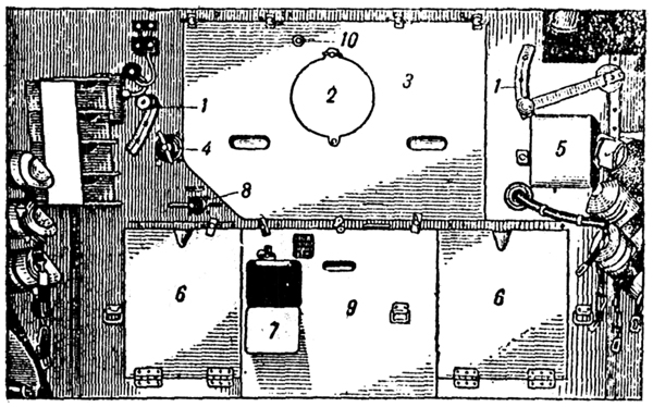
Plate 2 - Engine Bulkhead
1. Hand lever for louvre control
2. Cover of the ventilating hatch
3. Upper central removeable plate
4. Threaded grease gun
5. Access door for fuse box
6. Access door for oil cock
7. Fuel distributor cock
8. Lower central removeable plate
9. Nut of steem valve
The transmission compartment is situated in the rear part of the tank; it contains the engine clutch with centrifugal ran, gearbox, steering clutches with brakes, electric starter, final drives with two fuel tanks. The floor of the transmission compartment is provided with two apertures at the side for draining fuel (these apertures are closed by threaded plugs on the outside) and one opening Jon thc middle under the gear box for draining off oil (this opening is closed by means of an armoured cover from the outside).
In the roof of the transmission compartment, over the fan there are air inlet louvres (Plate 3). These are provided with a metal netting for keeping out foreign bodies. These are two access plates in the roof for the fuel tanks and filler plugs.
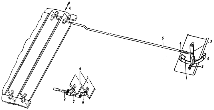
Plate 3 - Air Louvre control linkage
1. Segment
2. Hand lever with lock
3. Eye
4. Lost motion device
5. Tie-rod
6. Eye
7. Tie-rod
8. Lever
9. Louvres
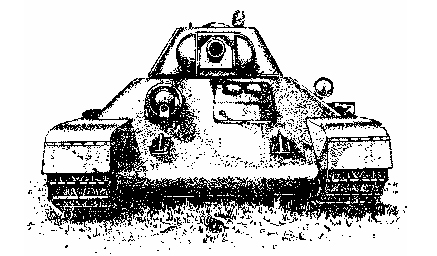
The Turret (Plate 4)
In the front of thc turret in a mantlet are installed: the 76 mm. gun and the co-axially mounted ATmachine gun and the telescopic sight TMOA-7. At the left of the gun on the turret neck the turret traversing gear is fitted.
The rear plate of the turret is removable. Fixed to the sides of the turret are the observation instruments and underneath them a revolver port is provided which is closed by means of a conical plug. This plug is inserted from the outside and pushed open by a steel lever. The rear part of the turret roof is fitted with an access hatch on the top of which there is a signal port. Fitted on to the front part of the roof are the instruments NTK-5 and NT-7 and between them a hatch is provided for ventilation which is covered by an armoured cap. The turret is prevented from coming off by turret clips. In the rear clip is incorporated a travelling lock for the turret.
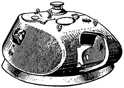
Plate 4 - Turret (front)
Door in the Access hatch of the Turret
In the closed position, the door (Plate 5) is secured by a lock (Plate 6) which is opened from the outside by a key. To open the lock from within it is necessary to press the catch (# 7), turn the lever (# 6) perpendicularly to the surface of the roof and pull the lever (# 4). In the open position, the roof is supported by a pawl (# 2). To close the roof it is necessary to press the knob (# 5) and remove the pawl. To facilitate the opening and shutting of the roof a balance spring (Plate 5) is provided.
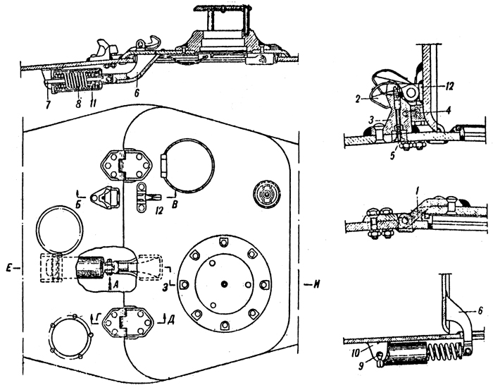
Plate 5 - Turret Access Hatch
1. Hinge
2. Pawl
3. Bracket
4. Rubber pad
5. Knob
6. Bracket
7. Lock
8. Spring
9. Pivot
10. Bracket
11. Casing
12. Hinge
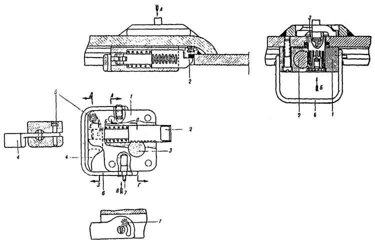
Plate 6 - Turret Hatch Lock
1. Body
2. Supporting shaft
3. Vertical shaft
4. Lever
5. Stud
6. Hand lever
7. Lock
Turret traversing Gear
The traversing gear enables the turret to be rotated either by hand or by means of the (electric motor clockwise or anti-clockwise. The construction of the traversing gear is shown in Plate 7.
Plate 6 - Turret Traversing Gear
1. Pinion
2. Cone friction clutch
3. Shaft
4. Planet carrier
5. Lower casing
6. Upper casing
7. Worm wheel for the hand wheel
8. Satellite wheels
9. Satellite pins
10. Pinion
11. Worm wheel for electric motor
12. Worm
13. Worm for handwheel
14. Handwheel
15. Electric motor
16. Driving pinion
17. Parasite pinion
18. Driven pinion
19. Rubber ring
20. Electric motor handwheel stop knob
21. Nut retaining the bodies
22. Packing disc for the lower casing
23. Disc with worm wheel
24. Cover
25. Electric motor control handwheel
To turn the turret by hand it is necessary to rotate the handwheel (# 14), in the direction required. To use the electric motor it is necessary to press knob (# 20) of the catch and turn the handwheel in the direction required. When the handwheel is in the neutral position, the catch returns automatically. The clutch spring of the gear (# 1), when in the fully compressed position, should measure 32-35.5 mm. long.
Ammunition Stowage
The ammunition is partly stowed in the fighting compartment and in the bulkhead partitions and partly in special boxes. There are six boxes of 9 rounds and two boxes of 7 rounds. In a11 there are 68 rounds.
Stowage of Ammunition in the Bulkhead partitions of the Fighting Compartment
In the right partition, 3 rounds and in the left, 6 rounds.
Stowage of MG Magazines.
In a fighting tank 75 magazines are stowed :
1. In the turret -26 magazines.
2. On the floor on the right hand side of the fighting compartment -8 magazines.
3. In the driving compartment -41 magazines.
In a fighting tank modified for wireless set, 62 magazines are stowed :
1. In the turret 26 magazines.
2. On the floor on the right hand side of the fighting compartment -8 magazines.
3. In the driving compartment 28 magazines.
In a tank with wireless set (Commander's tank), 46 magazines are stowed :
1. In the turret -26 magazines.
2. On the floor on the right hand side of the fighting compartment-8 magazines.
3. In the driving compartment 12 magazines.
Chapter II. SHORT DESCRIPTION OF THE ENGINE
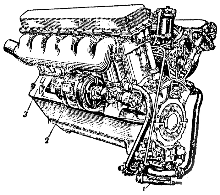
Plate 8 - V-2 Engine
1. Water pump
2. Generator
3. Engine bearer
The V-2 engine (Plates 8 and 9) is a four stroke compression ignition engine, water cooled with twelve cylinders at an angle of 60 degrees in two banks. The maximum capacity of the engine is 500 H.P. at 1,800 rpm.
The aluminium alloy crankcase consists of two parts joined together along the line of the crankshaft. On the crankcase top half are cast the cross webs which carry eight main bearings. The main bearings consist of steel shells lined with lead bronze. On the outside of the crankcase top half are fixed the cylinder blocks. Each bank consists of a block of six cylinders integrally cast and a detachable cylinder head. Wet liners are used. The joint between the cylinder head and liners is filled by an aluminium gasket. The lower joint between the jacket and liners is sealed with rubber jointing rings.
Four valves are used per cylinder, two are inlet and two are exhaust (Plate 9). The valves are controlled by the action of the camshaft (#61). Two overhead camshafts are used per blocks supported in seven bearings, and coupled by gears. One shaft is for the inlet valves and one for the exhaust valves. The cams operate directly on mushroom followers secured to the valve stems. At the end of the right hand valve covers (Plate 8) is fitted the tachometer drive which is taken of the inlet camshaft.
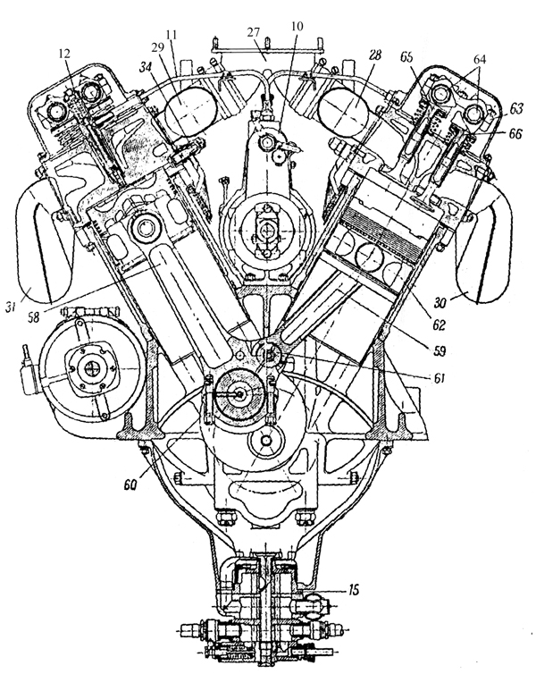
Plate 9 - V-2 Engine
10. fuel injection pump
11. High pressure tube to injectors
12. Injectors
15. Oil pump
27. Central tube for inlet manifolds
28 and 29. Inlet manifolds
3O and 31. Exhaust manifolds
34. Starting valve
58. Master rod
59. Articulated rod
60. Big end securing pins
61. Wrist pin
62. Piston
63. Ball bearing of cam shaft
64. Cam shaft
65. Inlet valve
66. Exhaust valve
The air enters into the cylinders of the engine through the central tube (#27), (Plate 9) which is joined to the inlet manifolds (#28 and #29). The products of the combustion are discharged from the cylinders into the air through the exhaust manifolds (#30 and #31).
The crankshaft has six throws arranged on three planes at angles of 120 degrees. Each throw has two webs of curved shape. The crank pins and main bearings, with the exception of the first main bearing are lubricated by oil through the drilled crankshaft. The end of the crankshaft is splined and onto it is fitted the clutch and fan.
The connecting rods of the V-2 engine, which are mounted on each crank pin are in pairs and consists of the master rod and the articulated rod. The articulated rods are fitted to pistons in the right bank. The master rods are secured to the crankshaft by means of lower detachable caps fixed by pins. The articulated rods are connected to the master rods by means of a wrist pin carried in lugs formed integrally with the back end of the master rod. The lower cap of the master rod is steel lined with lead bronze. In the little ends of both connecting rods bronze bushes arc used for the gudgeon pin bearings. The gudgeon pins are the floating type which are prevented from scoring the cylinder walls by two aluminium caps fixed at each end of the gudgeon pin. The pistons are of forged duraluminium and are provided with five piston rings. The upper four are gas sealing rings and the bottom one is an oil scraper. The piston crown has a special shape to suit the characteristics of the fuel injectors.
The fuel reaches the injector through a thick-walled steel tube (#11) (Plate 9) from the fuel injection pump (#10). In conformity with the load of the engine, the fuel injection pump measures out the correct quantity of fuel and forces it to the injectors under high pressure. The fuel injection pump is situated on the engine between the two banks. The fuel is forced to the fuel injection pump from the tanks by means of a fuel feed pump of the rotary type. Between the fuel feed pump and the fuel injection pump there is a filter, which is situated in the front of the engine between the two banks. This filter cleans the fuel before it enters the fuel injection pump.
The lubrication of the engine is by pressure pump and a dry sump is used. The oil pump (#15) (Plate 9) is attached to the crank case lower half and has three pairs of gears of which one pair functions as a pressure pump, and the other two pairs as scavenge pumps. The oil from the pump reaches the engine through a filter attached to the crankcase lower half.
Cooling water circulates in the jacket of the cylinder blocks under pressure of a centrifugal pump. This water pump 1 (Plate 8) is fastened to the crank-case lower half.
The engine can be started by an electric starter or by compressed air. The electric starter is fitted to the gearbox. An air distributor is attached to the front part of the engine for compressed air starting. From the air distributor compressed air is conveyed trough a steel tube to the starting valves fit too. inside the cylinder head.
The electric generator is carried on a cradle cast into the side of the crankcase top half and is driven by a slipping clutch.
Transmission of the drive to the camshafts and the subsidiary engine assemblies is carried out by means of a bevel positioned on splines at the tail and of the crankshaft. This bevel is in mesh with bevels on the upper and lower vertical shafts. The lower vertical shaft transmits the drive to the shaft of the water and oil pumps and the fuel feed pump. The upper vertical shaft transmits the drive to the air distributor cam, camshaft of the fuel injection pump and at the same time transmits the drive to the inclined shafts which actuate the cam shafts. The electric generator is also driven off the camshaft timing bevel.
The engine rests on a chassis in the tank on four bearers 3, (Plate 8) cast in one piece with the crankcase top half.
The Fuel System
The engine fuels are "Gas Oil" Mark E or diesel fuel "DT". Plate 10 shows the main fuel feed layout.
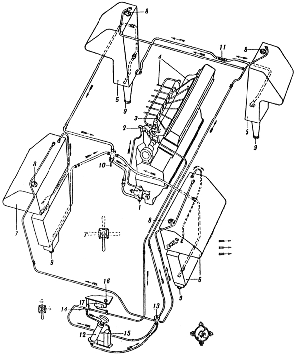
Plate 10 - Fuel System
1. Fuel feed pump
2. Fuel filter
3. Fuel injection pump
4. High pressure fuel pipe
5. Feed tanks
6. Front left tank
7. Front right tank
8. Filter caps
9. Drain plugs
10. Fuel distributor cocks
11. Auxiliary cock
12. Air pump
13. Air distributor valve
14. Bleeder cock
15. Bleeder tank
16. Pressure gauge
17. Compensation tank
The system consists of fuel tanks (#5 and #6), fuel feed pump (#1), fuel filter (#2), fuel injection pump (#3), injectors, pipe to fuel injection pump and air cleaner; and besides this the system also consists of cocks, fuel pipes, pressure gauge, compensation tank, small bleeder tank, and an air pressure pump.
Construction of Engine Fuel Feed System
Fuel tanks
In the early models six fuel tanks arc installed at the sides, of those the four front tanks are arranged in pairs in the fighting compartment and two are placed in the rear of the vehicle. In later models there are two more tanks of 75 litres each at the side of the engine compartment. The complete capacity of the fuel tanks is 460 litres. This capacity is divided up thus: front right and left tanks - 150 litres each and the rear tanks - 80 litres each. Besides this there are four spare tanks with 33.5 litres each attached on the outside of the inclined plates of the side hull.
Fuel from the front small feed tanks reach the distributor cock (#10) (Plate 10) through a flange welded to the back of the holder of the lower tank.
The fuel fillers of the front tanks are provided with mesh filters and are closed by plugs. On the top of each upper tank a pipe is introduced which passes through the air distributor cock (#13) to the air pressure pump (#12).
To measure the quantity of fuel in the front tanks there is a , dipstick which is pushed through the filler of the upper tank, to do this the mesh filter has to be removed. The dipstick indicates the approximate quantity of fuel in the upper and lower tanks.
The feed tanks are likewise provided with aperture for filling and draining. These apertures are closed by plugs. The feed tanks are connected by a cross pipe in which is fitted an auxiliary cock (#11) (Plate 10). From the back of the right feed tank there is a pipe which leads off horizontally along the right side of thc hull to the fuel cock.
From the top of the right and left feed tanks a pipe leads to the air pressure pump.
When the engine is running, the fuel is taken only from the right feed tank. The fuel flows simultaneously from both feed tanks if the auxiliary cook (#11) is opened. In the event of a defect in the right feed tank it becomes necessary to operate this cock. In this case it is necessary to turn the cock on the union pipe in order to conserve the fuel in the left tank. The full capacity of each feed is 86 litres. The level of the feed tanks can be tested with the same dipstick as for the other tanks using the other side of it.
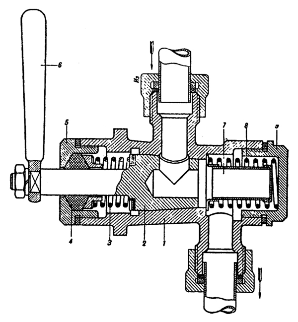
Plate 11 - Fuel distribution cock
1. Body
2. Plug
5. Nut
6. Hand lever
7. Mesh filter
8. Spring
9. Nut
The fuel distributor cock (Plate 11).
The cock serves the purpose of turning on or off the flow of fuel from the tanks to the engine. It is situated on the engine bulkhead at the right. Inside the body of the distributor cock there is a filter (#7) by means of which the fuel is cleaned before reaching the fuel feed pump. The body of the cock has four unions, of these three carry pipes from the fuel tanks and to the fourth is attached the pipe leading to the fuel feed pump. The handle of the tap has four positions (Plate 10):
1. Handle pointing down - tanks shut off
2. Handle to the left - petrol flows from front left tank.
3. Handle to the right - petrol flows from front right tank.
4. Handle pointing upwards - petrol flows from feed tanks.
The positions right and left are taken facing the front of the vehicle.
From the cock 10 (Plate 10) the fuel flows to the fuel feed pump 1. The fuel feed pump ensures the transmission of fuel under pressure from the tanks through the filter to the fuel injection pump. It is mounted in the crank-case on the fighting compartment side. For lubricating the gland of the fuel feed pump there is a nipple.
The filter 2 (Plate 10) is attached to the front of the engine between the two banks. From the filter a pipe leads off to the pressure gauge. The pressure gauge which measures the pressure of the fuel at the filter is mounted in the instrument panel in the driving compartment.
(This plate is currently unavailable)
Plate 12 - Fuel injection pump
1. Fuel priming lever
2. Support of fuel priming lever
3. Rack bar limiter
4. Rack bar
5. Nut of rack bar limiter
6. Split pin securing nut
7. Control plug of governor casing
8. Union for filler pipe
9. Lubricator for governor
10. Air bleeder plug
11. oil measurer
12. Drilling
Fuel injection
(Plate 12)
The pump is designed to measure out a fixed proportion of fuel corresponding to the load of the engine and to transmit it under high pressure through the injectors into the cylinders. The fuel injection pump is situated on the engine between the two banks.
Beginning at 1800-1850 rpm the governor controlling the action of the rack bar 4 of the pump limits the maximum engine revolutions. The maximum number of revs that the governor allows in the advent of a sudden falling off of load does not exceed 2050 per minute. The governor is adjusted so that the engine speed reaches 1800 rpm when working at its maximum capacity. The limiting stop of the stroke of the rack bar and the limiter of the fuel priming lever are sealed. It is categorically forbidden to remove the lead seals and change the setting of the limiters.
Lubrication of the components of the fuel injection pump is carried out by means or an oil filler hole in the top of the body of the pump. The oil level in the body of the pump is measured by a dipstick fitted to the filler hole. The normal oil level is between the upper and lower graduations. The pistons and cylinders of the fuel injection pump are lubricated directly from the fuel itself. The governor is lubricated by oil, filled into a casing through the lubricator (#9) {Plate 12) which is fitted to the upper casing of the governor. Oil should be filled into thc casing of the governor up to the level of the control plug (#7).
The fuel reaches the injectors (#8) (Plate 13) from thc fuel injection pump through a thick-walled steel tube.
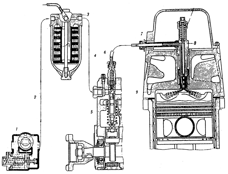
Plate 13 - Layout of fuel system
1. fuel feed pump
2. Low pressure pipe
3. Fuel filter
4. Low pressure pump
5. Fuel injection pump type HK-1
6. High pressure pipe
7. Injector union
8. Injector
9. Combustion chamber
Air Pressure Pump
Before starting the engine it is necessary to have the filter and all pipes leading from the tanks to the fuel injection pump primed with fuel. This entails the transmission of fuel from the tanks to the fuel feed pump. The pressure necessary to do this is 0.2-0.3 atmospheres. The hand operated air pressure pump (Plate 14) which is fitted in the front or the vehicle is used to supply this necessary pressure in the tanks. From this pump (#12) (Plate 10) a pipe leads to thc air cock (#13).
Air distributor cock The cock is fitted on the left of the driver. Its purpose is to link the appropriate fuel tank to the air pressure pump in order to put it under pressure for starting purposes and also to connect the tanks to the atmosphere during the time the engine is running.
The cock has five unions. To one union, the lower one, is connected the pipe from the air pressure pump, to three unions are connected pipes from the fuel tanks and one is connected to the bleeder tap
By turning the handle of the cock, one or the other of the fuel tanks can be connected to the air pressure pump, the remaining tanks are joined to the atmosphere through the opening in the body of the cock. When the position of the handle is against "MA" all the tanks are connected to the atmosphere and the air pressure pump to the air outlet cock. The other positions of the handle are marked thus:
# "J" - Left tank.
# "N" - Right tank.
# "3" - Feed tanks.
For bleeding the air from the fuel filter and the fuel injection pump there is a small tap on the instrument panel (#14) (Plate 10). Air can reach the fuel filter and fuel pump either when stationary owing to there being no fuel in the pipes or when moving through the pipes being air locked when the tanks are low.
The bleeder tap consistes of a three-way cock with three unions. The unions connect pipes leading from the fuel filter, air pressure pump and the small bleeder tank.
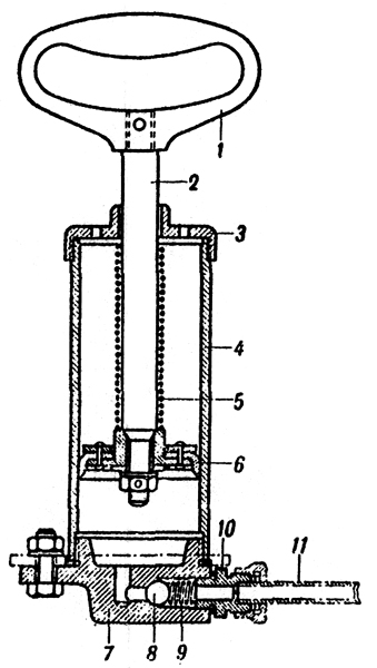
Plate 14 - Air pressure pump
1. Hand lever
2. Rod
3. Upper cap
4. Body
5. Spring
6. Piston
7. Lower body
8. Ball
9. Valve spring
10. Adaptor
11. Pipe
To expel air from the fuel filter before starting it is necessary to build up a pressure of 0.2- 0.3 Kg/cm2 in the tank which is switched on by the distributor cook and to turn the bleeder tap to the position marked "CIIYCK BO3AYXA"(Air out). (See plate 10 and the plate on the instrument panel). Under force of the pressure created in the tank, air, and afterwards fuel, goes from the fuel filter through a small tube, passing the pressure gauge, to the bleeder cock and through this to the bleeder tank. Air first goes through into the bleeder tank, then fuel and air and finally, only pure fuel. In order to eliminate air bubbles it is necessary for the handle of the tap to be in the working position (pointing downwards). If all the air has not been successfully removed from the fuel injection pump by means of the bleeder tap then it is necessary to open the engine hatch and withdraw the plug 10 (Plate 12). After releasing the air from the pump the plug should be replaced.
The position !IIPOAYBKA' (inflate) of the bleeder tap should only be used if the fuel oil congeals in the pipe leading to the pressure gauge. To blow out this pipe it is necessary to disconnect it from the fuel filter, set the handle of the bleeder tap to "IIPOAYBKA" and the air cock to "MA" and blow the pipe out by means of the air pump. The small bleeder tank is painted yellow and is positioned in the nose of the hull behind the instrument panel.
Fuel injection pump controls The fuel injection pump controls regulate the quantity of fuel entering the cylinders. The lay-out of the control system is seen in (Plate 15)
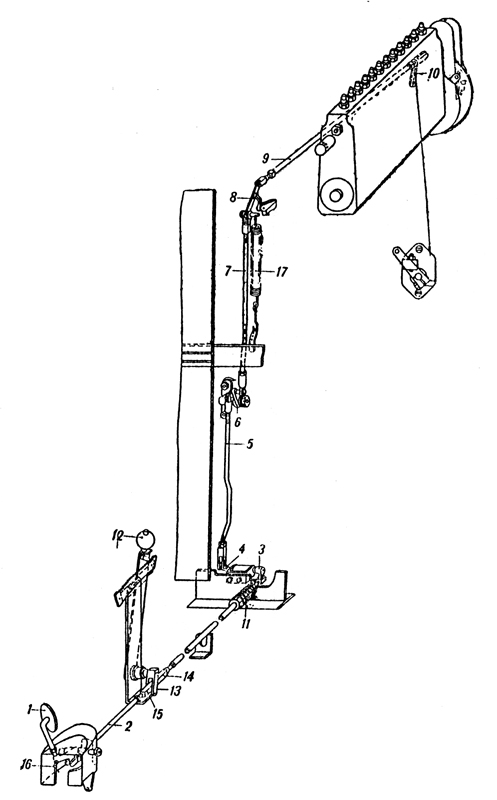
Plate 15 - Fuel injection pump controls
1. Foot pedal
2. Tie-rod
3. Lever on the lower bracket
4. Lever
5. Lower vertical tie-rod
6. Upper lever
7. Upper vertical shaft
8. Lover
9. Tie-rod
10. Forked lever
11. Spring
12. Hand lever
13. Fork
14. Support for rod
15. Rod
16. Supporting bolt
17. Vertical spring
On depressing the pedal (#1) the fuel priming lever on the fuel injection pump is operated by means of a system of tie rods and levers.
On releasing the pedal the spring (#11) returns the control to its original. position provided that the hand lever (#12) does not limit the movement of the tie-rod (#2). The hand lever (#12) is set to a minimum number of engine revs so that on releasing the pedal the engine will not fade.
Adjusting the fuel injection pump controls
1. Disconnect the tie-rod (#2).
2. Pull the fuel supply hand lever (#12) right back.
3. Alter the length of the tie-rod (#2), set the lost motion device (#10) to the extreme rear so that it is in the zero position (the lever resting on the body of the pump).
4. With the pedal pushed right down (so that it rests on the footboard) join the front end of the tie-rod (#2) to the pedal (#1).
5. With the bolt (#16) set the pedal (#1) to the extreme forward position so that the fuel supply lever on the pump reaches the stop (#2) (Plate 12) of the set screw.
6. Test to see that the travel of the horizontal tie-rod is 18-20 mm.
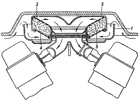
Plate 16 - Air Cleaner
1. Air Cleaner.
2. Lower vessel
3. Upper detachable cover.
4. Upper mesh
5. Lower mesh
6. Wire wool.
Air Cleaner
(Plate 16)
The air cleaner serves to purify the air from dust before it enters the cylinders. The air cleaner is supported on brackets welded to the inlet manifold. Thc basic filter element is oiled wire wool. Tanks of the latest modal (with V-2 engine) also have in the transmission compartment two "Cyclone" air cleaners.
Action of the engine feed system
When the engine is running the fuel feed pump of the rotary type 1 (Plate 13) supplies fuel from the tank to the fuel filter 3 under a pressure of 0.5 -0.7 Kg/cm2. The filtered fuel goes on to the fuel injection pump 5. In conformity with the firing order and the load of the engine, the fuel injection pump forces at high pressure the necessary quantity of fuel into the injectors. Maintenance of the engine fuel system. The main defects of the fuel feed system are due to obstructions in the fuel pipes owing to bad engine maintainece. The following points must be watched :
1. In filling the tanks with fuel attention must be paid to the instructions given in chapter VII under the heading "Filling up".
2. Every time the vehicle returns from a journey it is necessary to test the tanks, cocks and examine the whole system for damage. To test the air tanks and pipes, apply a pressure of 0.2-0.3 Kg/cm2 and watch the pressure gauge for 2-3 minutes. If after this period the pressure does not subside then there is something wrong with the system.
3. After every 10 hours of engine running it is necessary to examine and clean the mesh filter (#7) (Plate 11) in the distributor cock.
4. After every 25 hours of engine running it is necessary to clean the fuel filter.
5. After every 50 hours of engine running, the fuel tank drain plugs should be unscrewed and sediment removed.
If any defects occur in the fuel injector pump, the fuel feed pump and the fuel injector pump should be detached and handed over to a base workshop or to a special fitter.
The air cleaner should be periodically cleaned. The period depends on the terrain and time of the year. In summer when the atmosphere is dust laden, the air cleaners should be cleaned and oiled after 10 hours of engine running. In the winter only after 20-25 engine running hours. The air cleaners should be cleaned with kerosine.
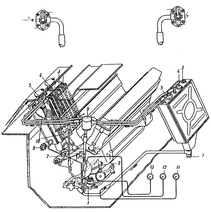
Plate 17 - Lubrication System
1. Oil pump
2. Oil radiator tank
5. Change-over cocks
6. Filler plug
7. Threaded grease guns for lubricating the spindle of the water pump
8. Compensating tank
9. Junction pipe
10. Fresh oil thermometer
11. Used oil thermometer
12. Pressure gauge
ENGINE LUBRICATION SYSTEM
For the lubrication of the engine, "Avia" Oil MK and M3 is used in the summer and M3L in the winter.
The lubrication system (Plate 17) consists of two oil radiator tanks 3, oil pump 1, oil filter 2, pressure gauge 13, two thermometers 11 and 12, and a compensating tank 9. In the latest models, oil tanks are not in the form of radiators (i.e. without cooling fins), and the change-over cock is not fitted.
Construction of Lubrication System The oil radiator tanks These are situated in the engine compartment at the sides. Their inner surfaces (facing the engine) are fitted with laminated fins (or radiator sections) where possible. The full capacity of each tank is 57 litres. The minimum possible quantity of oil is 10 -15 litres. A dipstick is provided and is inserted in the filler plug in the oil tank. In the bottom part of the tank there is an oil filter. At the base of the filter there is a threaded drain plug 7. To remove the oil from the tank this plug should be unscrewed two or three turns - it is not necessary to unscrew it completely - and the oil will flow from the opening. The inside of the plug is adapted to take a hose for draining the oil into a vessel. The filler has a mesh filter. The top of the tank has a change-over cock the handle of which has three positions:
1. Forwards (towards the front of the vehicle) - oil can be forced directly by the pump through the cock into the tank. 2. Backwards - radiator on. The oil is cooled to air temperature as it flows through the radiator fins and it passes into the oil tank to be taken up again into the engine. 3. To the side - the tank and radiator are shut off.
When the engine is running the handles of the change-over cocks 5 (Plate 17) of both tanks (those which have radiators) must either be in the position "HA BAKN" (to tank) or "HA PADNATOR" (to radiator), it is forbidden to leave the handle pointing to the side.
The junction tube 10 serves to connect both tanks to the crankcase and also to drain off oil and foam when the tanks are overfull.
The oil pump which is fixed to the crankcase bottom half serves to force oil under pressure to the engine and to scavenge the used oil.
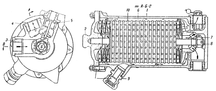
Plate 18 - Oil Filter
1. Body
2. Cap
3. Adaptor for inlet pipe
4. Adaptor for outlet pipe
5. Union for safety valve
6. Filter disc with rim outside
7. Nut
8. Central stud
9. Union
10. Filter disc with rim inside.
The oil filter (Plate 18) is attached to the front of the crankcase bottom half.
Action of the lubrication system
Both pairs of scavenge gears in the oil pump force oil into the compensation tank (#9) (Plate 17) whence it flows through the change-over cock (#5) into the tank-radiators. The compensation tank serves to return the used oil equally to both tanks. The pressure of the oil system which is indicated in the pressure gauge must be 6-9 Kg/cm2. This oil pressure is obtained by the help of the relief valve situated underneath the top or the oil pump. The temperature of the oil entering the engine (thermometer #11) must be more than 40oC and must not exceed 80oC The temperature of the oil leaving the engine (thermometer #12) must not exceed 100C.
In certain exigencies it is possible to fill not more than 5-6 litres of oil directly into the crankcase through the breather. The spindle of the water pump should be lubricated periodically by thc threaded grease gun (#3) (Plate 17).
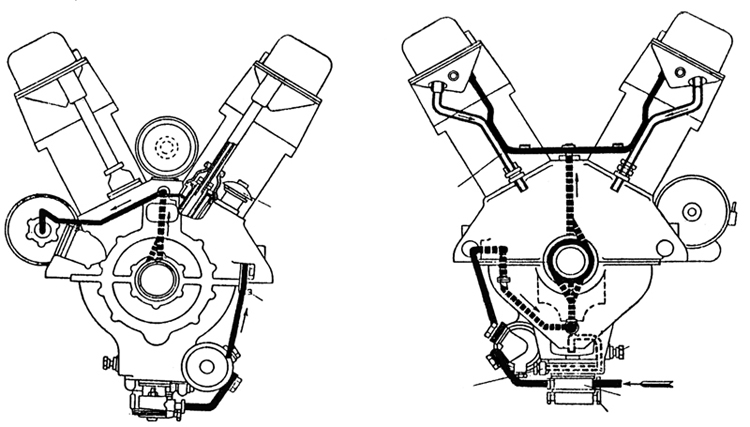
Plate 19 - Plan of Engine Lubrication
N.B. In V-2 -S4 (Series H) engines, the lubrication is conducted from the front.
ENGINE COOLING SYSTEM
The engine cooling system (Plate 20) is comprised of the water jacket of the cylinder blocks, water radiator (#1), water pump (#2) with cock (#3), centrifugal fan (#14), T-piece (#8) with air valve, steam valve (#12) and pipes. The capacity of the cooling system is 90-95 litres.
Construction of the Cooling System
Radiators
Two tubular type radiators are installed in the vehicle inclined at each side of the engine.
Each radiator consists of two collector tanks at the top and bottom connected to each other by copper tubes. To increase the cooling surface of these tubes, they are covered with thin copper laminations.
The lower collector tank of the radiators are joined by pipes to the water pump.
The top collector tank of the radiator has two pipe connections, one to the jacket, the other to the T-piece for draining water from the radiator. In the middle of this collector tank there is a union to which is joined to a thermometer. The top right collector tank has, in addition to these pipe connections, yet another pipe for leading off steam to the steam valve and an inspection plug for testing the level of the water.
The centrifugal fan is mounted on the flywheel and servee to blow air round the water and oil radiators.
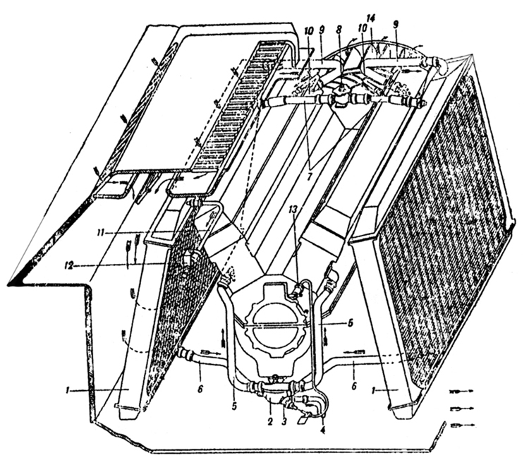
Plate 20 - Engine Cooling System
1. Water radiators
2. Water pump
3. Drain cock
4. Drain pipe
5. Pipes
6. Pipes supplying the pump
7. Hose connection ("durite") for filter
8. Filler T-piece
9. Pipes taking water from engine
10. Pipes taking steam from the cylinder heads
11. Pipe for taking off steam from the radiators
12. Steam valve
13. Lead to drain cock
14. Centrifugal fan.
The air valve with T-piece filler (#1) (Plate 21) is connected to both radiators and is designed for filling up with water. In the cover of the T-piece an air valve is fitted adjusted to operate at pressures of 0.08- 0.13 Kg/cm2 lower than atmosphere. Thus it is impossible for a pressure lower than atmosphere to form inside the radiator as a result of the rapid cooling of the system when the engine is stopped.
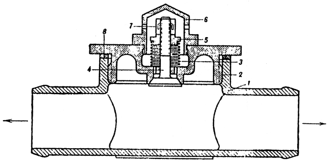
Plate 21 - Filler T-piece with air valve
1. T-piece
2. Body of air valve
3. Spring
4. Valve
5. Nut
6. Cap
7. Split pin
8. Packing
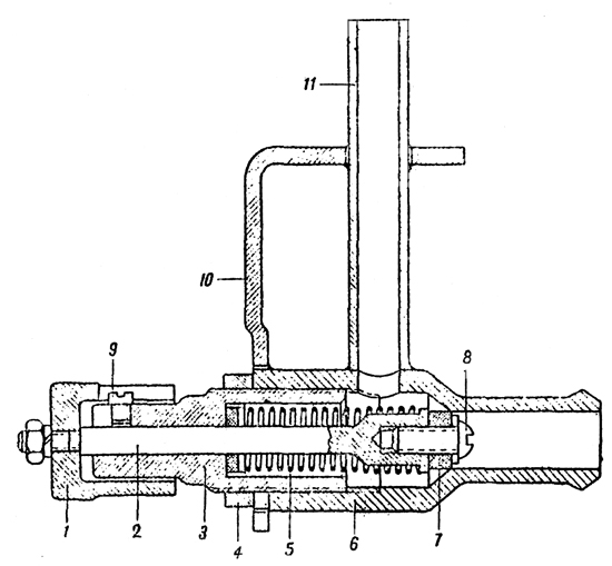
Plate 22 - Steam Valve
1. Nut
2. Valve spindle
3. Adjusting nut
4. Chock nut
5. Spring
6. Body of valve
7. Rubber valve
8. and 9. Screws
10. Bracket
11. Steam escape pipe
The steam valve (Plate 22) is fitted to the upper half of the engine Compartment bulkhead. The body of the valve is connected to the steam escape pipe of the right radiator. The steam outlet pipe (#11) of the valve leads outside through a hole in the hull of the tank.
The nut (#1) of the valve serves as a control and is situated inside the fighting compartment.
The steam valve is adjusted to open at pressures of 0.6-0.8 atmospheres above atmospheric pressure, thereby safe-guarding the radiators from internal pressure.
When filling up and draining off water, it in necessary to turn the nut (#1) to the right or left so that the cooling system is connected to the atmosphere. When filling up or draining off is finished. the steam valve must be closed again by screwing up the nut.
Starting up the engine by compressed air The compressed air system is an alternative method of starting the engine and is used when the electric starter will not work.
CONSTRUCTION AND ACTION OF COMPRESSED AIR STARTING SYSTEM
The system of starting the engine by compressed air (Plate 23) consists of two compressed air bottles, a reduction valve (#8), pressure gauge (#9), air distributor to cylinders (#12) (mounted on the engine), pipes (#13) from the air distributor to cylinders and twelve outlet valves (one for each cylinder).
The compressed air bottles are fitted on special brackets (#2) in the nose of the tank.
The capacity of each bottle is 10 litres and the maximum pressure in the bottle is 150 atmospheres. Each bottle has a valve by means of which it is connected to the control system. Air from the bottles travels through the pipe (#4) to the T-piece (#5) and to the reduction valve.
The T-piece is designed for refilling the bottles with air without removing them from the vehicle.
The reduction valve (#8) is designed for adjusting the air pressure at the air distributor of the engine. It is mounted at the left of the driver.
The pressure gauge which reads up to 250 atmospheres indicates the pressure in the bottles (when the valves are opened). Procedure for starting the engine by compressed air is described in Chapter VII - Maintenance.
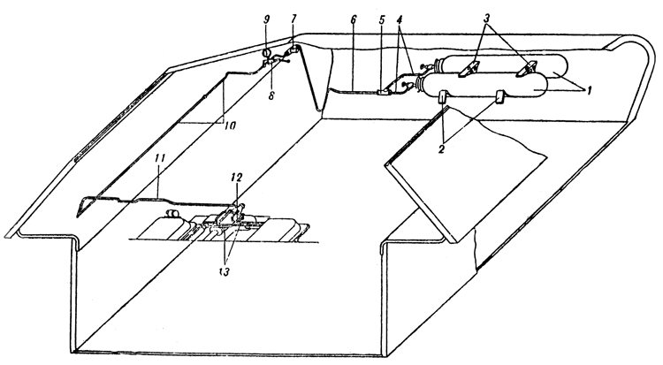
Plate 23 - Layout of Compressed Air Starting System
1. Compressed air bottles
2. Brackets
3. Clamps
4. Pipes
5. T-piece
6. Pipe Connecting T-piece
7. T-piece for filling air bottles
8. Reduction valve
9. Pressure gauge
10. Pipe
11. Transverse pipe
12. Air distributor
13. Pipes connecting air distributor to cylinders.
Care of the Compressed Air Starting System
It is necessary to test the air pressure in the bottles periodically during inspection of the vehicle.
The pressures in the bottles must not be lower than 40 atmospheres in the summer and not lower than 60 atmospheres in the winter. The pressures should be increased in the case of a worn engine. If the pressure is lower than instructed, starting will be made more difficult.
INSTRUMENT PANEL
The instrument panel carries the following instruments :
1. Two pressure gauges of which one indicates the fuel pressure and the other the oil pressure.
2. Three aero-thermometers of which one indicates the temperature of the oil entering the engine, one the temperature of the oil leaving the engine and the third the temperature of the water leaving the engine .
3. Tachometer showing the revs of the crankshaft.
4. Clock. A speedometer is mounted on the suspension casing of the left front bogie wheel.
Chapter III. TRANSMISSION
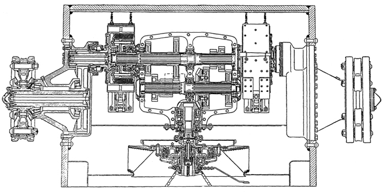
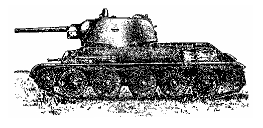
Plate 24 - Transmission of the tank
ENGINE CLUTCH
The engine clutch is multiplate, dry with steel friction plates. It consists of driving and driven parts and a withdrawal mechanism. The operation of the clutch from the driving compartment is carried out by means of a linkage (Plate 26).
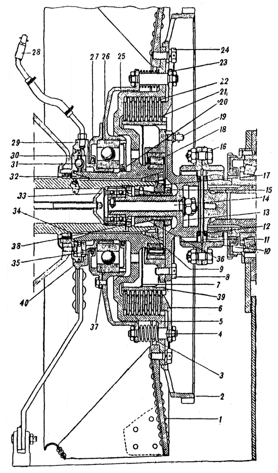
Plate 25 - Engine Clutch
1. Fan
2. Starter ring
3. Spring
4. Stud
5. Flywheel
6. Pressure plate
7. Oil excluder plate
8. Bolt
9. Cone
10. Coupling
11. Ring
12. Packing
13. Hub
14. Scouring bolt
15. Nut
16. Fitted bolts
17. Plug
18. Roller bearing
19. Lubricator
20. Gland
21. Driven plate
22. Driving plate
23. Lock washer
24. Bolt
25. Disengaging plate
26. Ball bearing
27. Cover
28. Lubricator
29. Control box
30. Fixed face cam
31. Ball of withdraw mechanism
32. Cone
33. Ball bearing
34. Packing
35. Gland
36. Conical plug
37. Packing
38. Nut
39. Driven drum
40. Cast iron ring
The driving plate of the clutch comprises of (Plate 25): flywheel (#5), disengaging plate (#25), pressure plate (#6) and ten steel driving plates (#22). The flywheel is seated on splines of the crankshaft, it is centered on it by two bronze cones (#9) and (#32) secured by a plug (#17) which is located by the cone (#36) tightened by the nut (#15) screwed on to its stem.
To safeguard against the cone moving and tightening the nut (#15), there is a dowel that fits into one of the slits of the plug (#17).
The internal surface of the flywheel is splined to mesh with the teeth of the driving plate (#22). Around the flywheel plate are positioned sixteen holes for the studs (#4). The fan (#1) is fitted to the flywheel plate on the side of the engine and on the side of the gearbox a toothed ring for the starter.
The fan is secured by 27 bolts, of which 24 are used to secure the toothed starter ring.
The disengaging plate (#25) and the pressure plate (#6) have sixteen holes. These plates (#25) and (#6) are joined to each other by the studs (#4) and are secured by nuts. The springs (#3) pressing against the friction plates are carried on the studs between the flywheel and disengaging plate. Between the shoulders of the studs (#4) and the pressure plate two washers (#13), 0.5 mm. are fitted. These washers are designed for the normal maintenance adjustment of the clutch.
The driving plates (#22) are made of steel; their outer circumferences are splined and are in mesh with the teeth of the flywheel. Thus all the driving components of the engine clutch rotate in one piece with the crankshaft.
The driven parts of the clutch comprise of: The driven drum (#39), with hub (#13) and twelve steel driven plates (#21).
The outer surface of the driven drum is splined and in mesh with the teeth of the driven plates. On the outside, the driven drum is connected to the hub, (the end of which is splined), by means of eight bolts.
The driven drum runs on a ball bearing (#18) seated on the hub of the flywheel. (In tanks of the first model the driven drum had two supports; a roller bearing on the hub of the flywheel and two ball bearings in the end of the crankshaft, through the tail piece of its hub, the driven drum rested on these bearings.
The connection between the driven drum and the driving shaft of the gearbox is in the form of a geared tooth coupling (#10). One half of the coupling meshes with the tooth of the hub (#13) and the other half with the gear of the driving shaft. Both: halves of the coupling are connected to one another by fitted bolts (#16).
The driven plates have teeth, the inside of which mesh with the toothed driven drum. All the driven plates of the engine clutch rotate in one piece with the driving shaft of the gearbox.
Withdrawal mechanism of the engine clutch comprises of:
# fixed face cam (#30)
# separator with three balls (#31)
# control box (#29).
The fixed face cam is bolted and doweled to the crankcase.
The control box is a press fit in the inner race of the ball bearing (#26) the outer race of which, is housed in a seating of the cover of the disengaging plate provided with felt ring oil seals. To the control box a grooved ring of special shape is fitted for balls. In the fixed face cam there are also grooves of the same shape on the other half of the face cam.
Between the fixed face cam and the control box there is a separator with balls which run in the grooves.
Note. In T-34 tanks with M-17 engine, the engine clutch is the BT type.
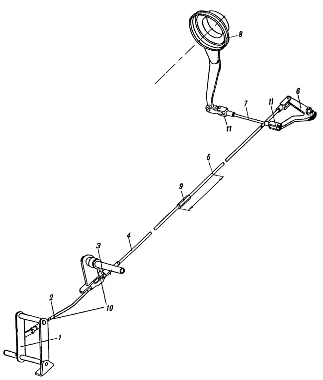
Plate 26 - Engine Clutch Control Linkage
1. Pedal
2. Inclined rod
3. Supporting lever
4. Front part of long tie-rod
5. Rear part of long tie-rod
6. Double arm lever
7. Transverse lever
8. Control box
9. Adjustment
10 & 11. Feed joints
Adjustment of the clutch. A. To adjust the clearance in the balls of the withdrawal mechanism to within 0.9 -1.1 mm. 1. Unscrew the nuts securing the spring loaded studs (#4). 2. Remove the pressure plate. 3. Remove one adjusting washer from each stud. 4. Replace pressure plate.
If the travel of the tie-rod measures from 20 - 25 mm then the clearance in the balls of the withdrawal mechanism will be from 0.9 -1.1 mm.
B. To adjust the travel of the pressure plate to 6 to 7 mm. 1. Adjust the fork (#10) on the inclined tie-rod. 2. Alter the adjusting nut (#9) on the long tie-rod.
GEAR BOX
Translator's Note: The gearbox is of normal sliding mesh type of a very usual design with four speeds forward and one reverse and it has not been considered necessary to make a full translation of its description.
The gearbox casting is of aluminium and made in two halves. Recently it has been made of cast iron.
It is operated by a selector mechanism (Plate 30) on the right of the driver to which is fitted a lock to prevent reverse gear being accidentally engaged when moving forward.
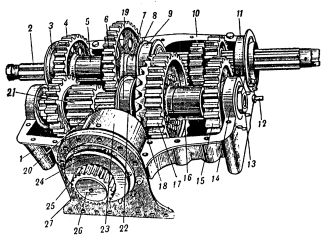
Plate 27 - General View Of The Gearbox (Without The Top Half Of Its Case)
1. Casing, lower half
2. Main shaft
3. Outer race of main shaft bearing
4. Fixed gear of 2nd speed
5. Spacer bush
6. Fixed gear of 1st speed .
7. Spacer bush
8. Ring of cover of conical bearing
9. Cover of conical roller bearing of central support
10. Moving gear train for 3rd and 4th speed
11. Cover of roller bearing of outside support
12. Limiter of control box for disengaging steering clutch
13. Nut
14. Roller bearing of outside support
15. Fixed gear of 3rd speed
16. Spacer bush
17. Fixed gear of 4th speed
18. Driven bevel gear
19. Cover of intermediate shaft
20. Intermediate shaft
21. Moving gear train for 1st and 2nd speeds
22. Driving bevel gear
23. Cover of driving shaft
24. Gland nut
25. Geared coupling
26. Plug
27. Bracket
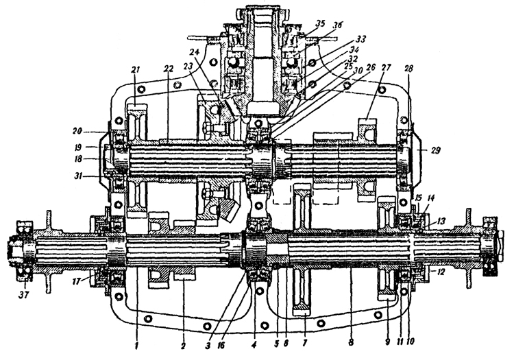
Plate 28 - Gearbox (Section Through Casing)
1. Main shaft
2. Gear train of 3rd and 4th speeds
3. Conical roller bearing
4. Cover of main shaft roller bearing
5. Nut
6. Spacer bush
7. Fixed (driven) gear of 1st speed
8. Spacer bush
9. Fixed gear of 2nd speed
10. Cover of outer supporting cylindrical roller bearing
11. Roller bearing
12. Packing ring
13. Ring
14. Gland
15. Fixed face cam of steering clutch disengaging mechanism
16. Thrust ring
17. Bush
18. Intermediate shaft
19. Nut
20. Roller bearing
21. Fixed gear of 3rd speed
22. Spacer bush
23. Fixed gear of 4th speed
24. Driven bevel gear
25. Cover of conical roller bearing of intermediate shaft
26. Conical roller bearing
27. 1st and 2nd speed gear train
28. Roller bearing
29. Cover
30. Thrust ring
31. Adapter ring
32. Driven shaft
33. Cover rim
34. Roller bearing
35. driven roller bearing
36. Ball bearing
37. Spherical ball bearing
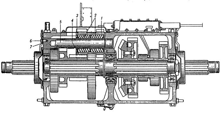
Plate 29 - Gearbox (Section Through Reverse Gear Train)
1. Reverse gear train
2. Roller bearing
3. Ring nut
4. Floating washer
5. Shaft of reverse gear train
6. Set screw
7. Plate
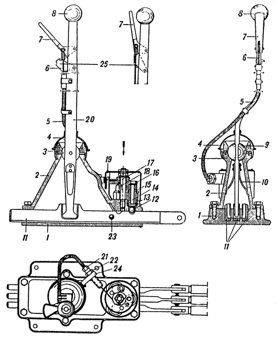
Plate 30 - Gear Selector
1. Base. of gear selector
2. Casing
3. Spherical nut
4. Protecting cover
5. Flexible cover
6. Cable
7. Locking handle
8. Gear selector hand lever
9. Ball and socket joint
10. Plate spring
11. Horizontal selector rods
12. Locking ball
13. Locking plugs
14. Locking catch
15. Looking spring
16. Rotating plate
17. Spindle of rotating plate
18. Return spring
19. Cover of locking gear
20. Gear lever
21. Bolt
22. Check nut
23. Ball of look
24. Bracket
25. Retaining latch for reverse gear
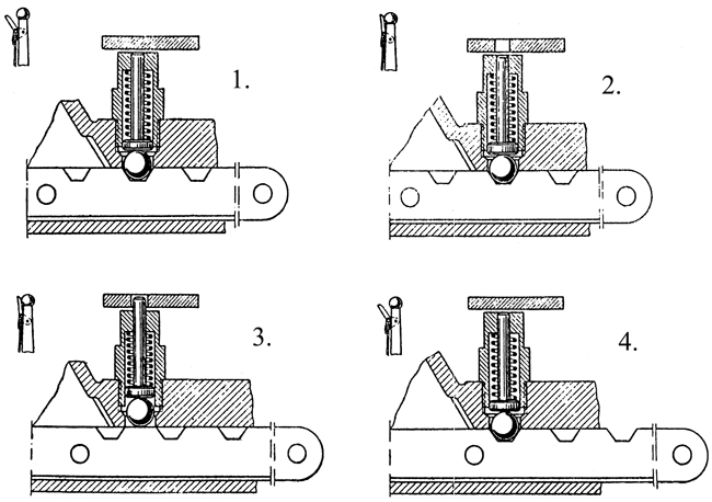
Plate 31 - Action Of Gear Selector Locking Device
# 1st Position Handle not compressed. The rotating plate does not allow the locking catch to move upwards.
# 2nd Position Handle compressed against the lever. The rotating plate is turned and an aperture is brought immediately over the catch.
# 3rd Position Handle compressed against the lever. On moving the horizontal lever the ball is forced up and the catch mates with the aperture in the rotating plate.
# 4th Position Gear engaged. ball returns to socket under pressure of the spring and rotating plate returns to normal position .
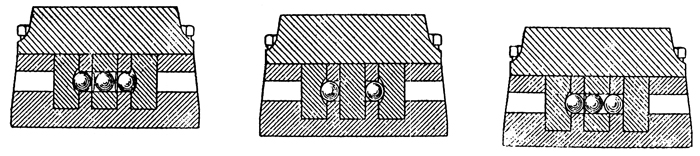
Plate 32 - Action Of Gear Selector Lock
1. Neutral.
2. Central horizontal lever is moved. End levers are closed.
3. Right horizontal lever moved. Central and left levers are closed.
Plate 33 - Vertical Shafts
1. Tie-rod of 3rd and 4th gears
2. Tie-rod of reverse gear
3. Tie-rod of 1st and 2nd gears
4. Bottom lever of reverse gear
6. Bottom lever of 1st and 2nd gears
7. Shaft of 1st and 2nd gears
8. Shaft of reverse gear
9. Shaft of 3rd and 4th gears
10. Top lever of 1st and 2nd gears
11. Top lever of reverse gear
12. Top lever of 3rd and 4th gears
13. Bracket
14. Lubricator
15. Tie-rod for 1st and 2nd gears
16. Tie-rod for reverse
17. Tie-rod for 3rd and 4th gears
18. Cranked lover for 3rd and 4th gears
19. Tie-rod for 3rd and 4th gears
20. Ball
22. Pin
STEERING CLUTCHES
The steering clutches are mounted on the main shaft of the gearbox. The internal driving drum (#3) (Plate 34) is splined on to the intermediate shaft of the gearbox, the external driven drum (#1) is fixed at the edges to the final drive. Between the internal and external drums there is a complete set of twenty-one driving and twenty-two driven plates each of which is geared to teeth of its corresponding drum.
The plates are compressed by springs (#19) acting through eighteen studs passing through openings of the plate of the internal, to the pressure plate (#2) seated on studs and fixed by nuts which are locked by flexible washers. The other extremity of the springs rest on the disengaging plate (#18) seated on the same studs and fixed by nuts. The withdrawal mechanism is operated by fixed face cams on the same principle as in the engine clutch (see drawings).
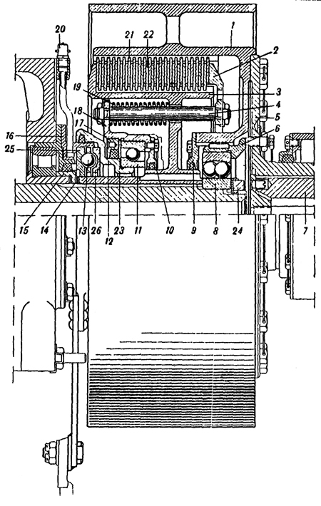
Plate 34 - Steering Clutch
1. External driven drum
2. Pressure plate
3. Internal driving drum
4. Stud
5. Steering clutch flange
6. Ring
7. driving shaft
8. Two-point spherical ball bearing
9 & 10. Caps with glands
11. Ball bearing supporting radially
12. Control box
13. Withdrawal mechanism ball
14. Adjustment
15. Ring
16. Fixed face cam
17. Stuffing box
18. Disengaging plate
19. Spring
20. Lubricator
21. Driven plate
22. Driving plate
23. Washer
24. Nut
25. Fixed face cam ring
26. Control box ring
BRAKES
The brakes which are used for parking, slowing down or steering are in the
form of "floating" bands which wrap round the outside of the driven end of the steering clutches. The steel bands are lined with Ferodo. In later models the internal surface of the brake bands have riveted cast iron linings.
The upper ends of the brake bands terminate in an adjusting bolt which is joined to a lug in the control lever and scoured by a pin.
The clearance between the brake band and the drum when the brakes are released should be maintained at 1.5 to 2.0 mm.
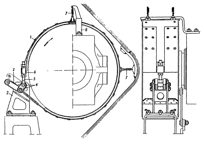
Plate 35 - Brake Band
1. Brake band
2. Actuating lever
3. Bracket
4. Pins
5. Adjusting bolt
6. Barrel Nut
7. Spring
8. Securing arm
CONTROL LINKAGE FOR STEERING CLUTCHES AND BRAKES
The control linkage for steering clutches and brakes (Plate 36), consists of the following main parts: steering levers (#1) with compensating device compensating shafts (#2) transfer shafts (#3) tie rods
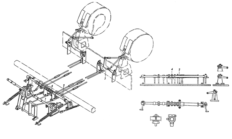
Plate 36 - Layout Of The Steering Clutch And Brake Controls
1. Steering lever with compensating mechanism
2. Compensating shaft
3. Transfer shaft
4. Foot bake control
The steering lever (#1) pivots on a shaft fixed in a bracket. This actuates a small lever (#4), of the foot brake linkage. This small lever is joined to the brake band through other levers connecting to the compensating shaft, tie-rods and levers of the transfer shaft.
The steering levers terminate in hooked levers, the internal working surfaces or which are ramped and bear against rollers fixed to a forked lever which is pivoted in the bracket. (Plate 37) One end of the forked levers is connected to a return spring and the other end to the control rod of the steering clutch. This tie-rod is connected through the compensating shaft, long tie-rod, transfer shaft and control lever to the control box of the steering clutch.
The connections between the separate components of the control linkage are shown in Plate 36.
The foot brake control consists of pedals, pedal tic-rods with two projections. One end of the pedal tie-rod is connected to the pedal and the other end to a small control lever (#4) which moves freely at the end of the two compensating shafts.
Action of the steering Control
When the steering lever is in the extreme forward position, the force of the compensating springs is transferred through the rollers to the bracket. On pulling the steering lever backwards the spring pulls the forked lever forwards and disengages the steering clutch. When the roller reaches the end of the ramp of the hook the disengagement of the clutch is completed and the force of the clutch spring is transferred to the bracket. All the force exerted by the driver is now used to operate the brake. A fixing device is provided to hold the brakes on.
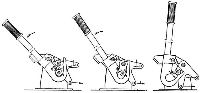
Plate 37 - Action Of The Steering Lever
A. Force of unloader spring.
B. Force of steering clutch spring.
The fixing device (Plate 33) consists of the following parts : bracket (#5), toothed segment (#6), control lead (#7) and return spring (#8).
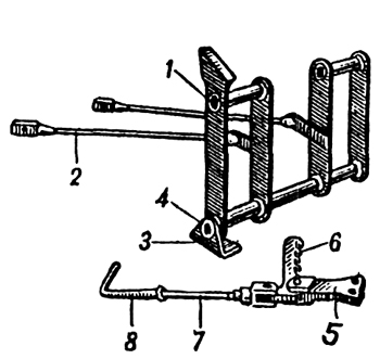
Plate 38 - Pedals Of Foot Brake And Engine Clutch With Fixing Device
1. Foot brake pedal
2. Tie-rod
3. Bracket
4. Shaft
5. Bracket
6. Toothed segment
7. Control lead
8. Spring
Adjustment to the Steering Clutches and Brakes and their Control Linkages 1. The clearance between the balls and the fixed face cam of the withdrawal mechanism of the steering clutch should be between 0.9 and 1.1 mm. 2. The travel (in one direction) of the long tie-rod of the steering clutches should be between the limits of 9 to 12 mm. 3. The clearance between the brake band and the drum should be within the limits of 1.5 to 2 mm. 4. The tie-rod should have 15 to 20 mm. horizontal travel before the brakes are applied.
FINAL DRIVE
The final drive (Plate 39) is mounted in casing (#16) incorporated into the tail of the tank and the hull side plates. The cover (#8) is attached to the casing by bolts. The final drive is a single hub reduction gear which transmits the torque to the sprocket wheel.
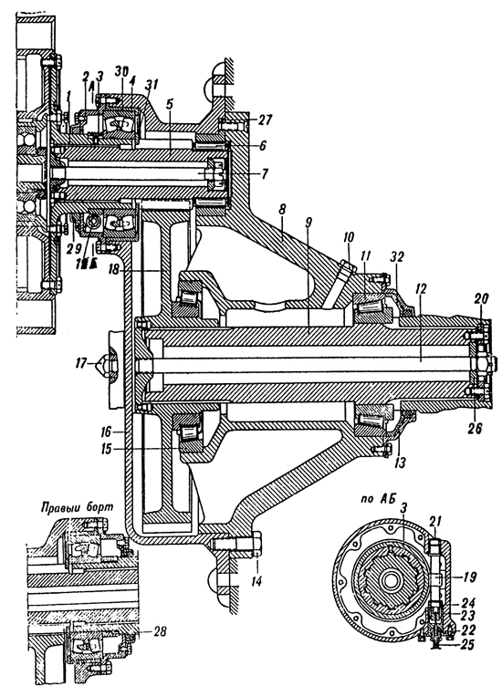
Plate 39 - Final Drive
1. Flange
2. Cover
3. Worm
4. Spherical roller bearing
5. Driving shaft with gear
6. Roller bearing
7. Assembly locking spindle
8. Cap of casing
9. Driven shaft
10. Filler plug
11. Conical roller bearing
12. Assembly locking spindle
13. Cap
14. Bolt
15. Conical roller bearing
16. Casing
17. Plug of lubricating aperture
18. Driven gear
19. Worm wheel shaft
20. Washer
21. Bush
22. Flanged bush
23. Internal bush
24. Sealing washer
25. Speedometer cable casing
26. Washer
27. Cover of roller bearing
28. Sealing ring
29. Gland
30. Cover of spherical roller bearing
31. Sealing ring
32. Pressure ring of gland
Maintenance of the Final Drive
1. After 500 km. disconnect the tracks, remove the cap of the sprocket wheel and test the assembly locking spindles (#2) for looseness. If necessary tighten up the nuts and slacken off 1/16 of a turn and re-fit with split pin.
2. After 1000 km. 1 kg of lubricant should be inserted through the opening in the cover of the casing and 2.5 kg into the greasing aperture. The lubricant should be 70% "Avia" oil and 30% "Konstalin".
Chapter IV. SUSPENSION
Sprocket Wheel
The tank has two sprocket wheels at the rear, each of identically the same design. The sprocket wheel is fitted to the splined end of the driving shaft of the final drive. The wheel is fixed by a ring (Plate 40) which is screwed by four studs to the end of the final drive shaft. The securing ring is covered by an armoured cap. The hub (#4) of the wheel has a flange. In later models the rims of the wheels are cast integrally with the discs and hubs. The discs (#5) of the wheel are bolted to the flange. The discs have six large exit holes for mud and snow and six seatings for the shafts of the rollers. To prolong the life of the rims, steel tyres (#2) are fitted. The shafts (#3) are housed between the discs and carry bronze bushes (#9) upon which the rollers rotate.
As the sprocket wheel rotate they drive the tracks by means of the rollers which bear against the guide horns.
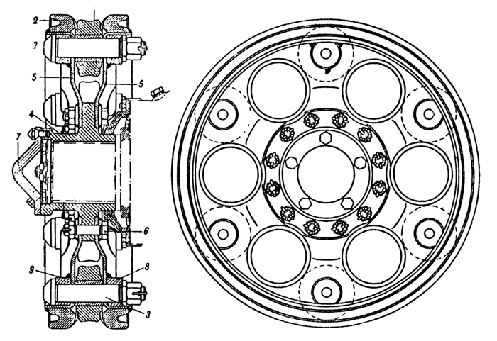
Plate 40 - Sprocket Wheel
2. Tyre
3. Roller shaft
4. Hub of wheel
5. Disc
6. Securing stud
7. Armoured cap
8. Adapter
9. Bush
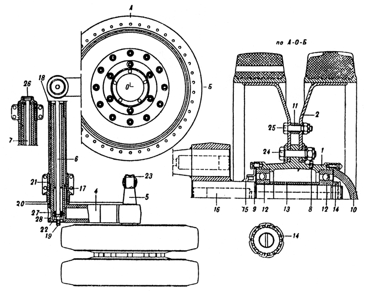
Plate 41 - Bogie Wheel
1. Hub
2. Disc
4. Suspension arm
5. Trunnion
6. Assembly looking spindle, 2nd, 3rd, and 5th bogies
7. Assembly looking spindle of 4th bogie
8. Lubricator
9. External labyrinth seal
10. Armoured cap
11. Bush
12. Ball bearing
13. Distance piece
14. Nut
15. Internal labyrinth seal
16. Bogie axle
17 & 18. Bushes
19. Lubrication aperture
20. Adjusting ring
21. Suspension arm shaft
22 & 23. Washers
24. Fitted bolt
25. Bolt
26. Internal cap of suspension arm tube of 4th bogie
27. Ring
28. Nut
Bogie Wheels and Cranks
All the bogie wheels are of the same design. In the hub 1 (Plate 11-1) of the bogie wheel are pressed in two ball bearings (#12). Between them there is a distance piece (#13). The bogie wheel is attached to the fixed by a nut (#14) with lock. The hub of the bogie wheel is covered by an armoured cap (#10). To the internal end of the hub is fastened a labyrinth seal consisting of two rings (#9) and (#15). on the outside of the hub there is a flange. The plates (#2) are fastened to the flange by bolts (#24). Between them the plates are supported by bolts (#25) which rest in bushes (#11). On the plates of the bogie wheel are pressed and welded steal rims with rubber tyres.
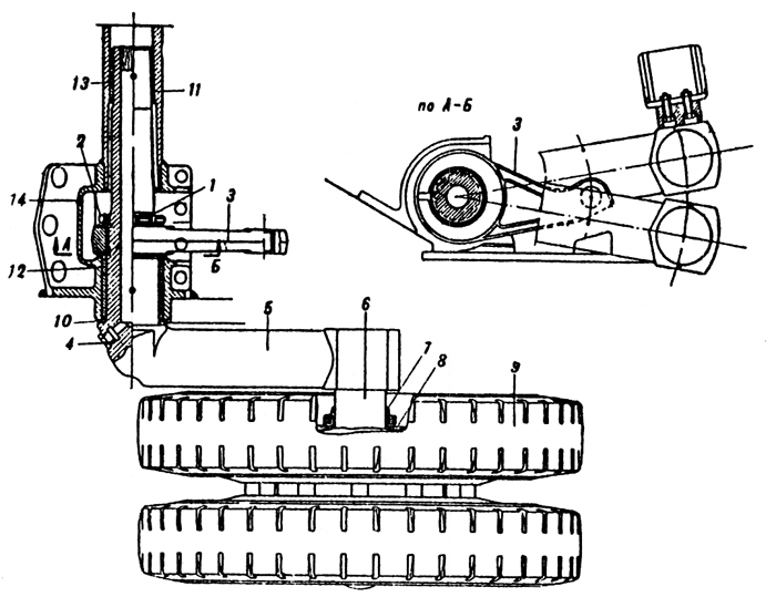
Plate 42 - Leading Bogie
1. Nut 2. Lock Washer 3. Lever 4. Lubricator hole 5. Suspension arm 6. Axle of wheel 7. Internal labyrinth seal 8. External ring 9. Rubber tyre 10. Adjusting ring 11. Front tube 12 & 13. Bronze bushes 14. Bracket
The cranks serve to connect the bogie wheels to the hull of the tank and to the springs. Each crank consists of a suspension arm and two axles i.e. the suspension arm axle and the axle of the bogie wheel. The axle of the suspension arm rests in the hull in cast iron or bronze bushes. The bogie wheel is carried on its axle by two ball bearings. When movement of the bogie wheel takes place as it goes over an obstacle the crank rotates around its axle in the hull and compresses the spring. On each side of the tank there are five cranks i.e. one for each bogie wheel. The cranks of the bogie wheels, with the exception of the front ones are of exactly the same design. The axle of the bogie wheel (#16), the axle of the suspension arm (#21) and the trunnion (#5) for the attachment of the springs are pressed into the suspension arm and welded.
The opposite cranks of both sides of the tank are linked by bolts (#6) which safeguard them from lateral displacement. The cranks of the front bogie wheels are made in one piece with the axles which are carried in the front of the hull (Plate 42).
TRACKS
Each track consists of 74 steel track links (Plate 43). Every other track link has a guide horn which serve to mesh with the sprocket wheel and hold the track in position. The track links are hinged to one another by 148 pins. The pins are prevented from falling out by keepers. Each track has holes for fastening additional spuds. The spuds (Plate 44) are fixed by two bolts to the track.
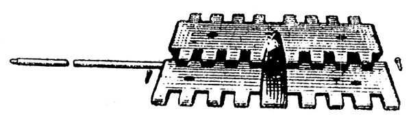
Plate 43 - Track link
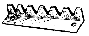
Plate 44 - Spud
Idler Wheel and Track Adjuster.
The idler wheel is situated in the front part of the tank and serves to adjust the torsion of the tracks. The axle of the idler wheel is made in the form of a crank. The idler wheel is secured to the crank on two ball bearings and is fixed by nuts (Plates 45 and 46). The hub of the wheel is covered by an armoured cap. On the surface of the wheel two rubber tyred rims are shrunk on and welded (on tanks of the latest model there is no rubber on the idler wheel).
The axle of the crank rests in a bracket welded to the hull of the tank. By means of special nuts and locking bolts the axle is attached from inside the tank.
The end of the crank is toothed to mesh with the teeth of the ring welded to the bracket.
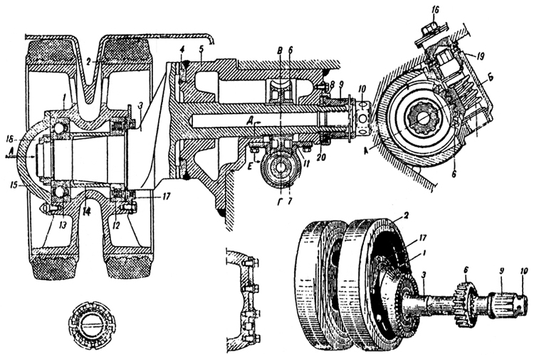
Plate 45 & 46 - Idler wheel and Track Adjuster
1. Body of wheel
2. Rubberized tyre
3. Crank
4. Toothed ring
5. Bracket
6. Worm wheel
7. Worm
8. Flange
9. Nut
10. Stop bolt
11. Casing of track adjuster
12. Roller bearing
13. Ball bearing
14. Spacer bush
15. Armoured cap
16. Armoured plug
17. Cover with gland
18. Castellated nut
19. Adjusting packing
20. Ring
Springs
Each bogie wheel has two separate springs. The springs of the leading bogie are different from these of the remainder. The springs of the leading bogies are of the coil type and one is situated inside the other (Plate 47). A rod travels inside the springs. This rod is attached to a lug which connects it to the crank lever by means of a pin. On the lower half of the rod is mounted the spring seating. The upper half of the rod travels in a guide bush in the adjusting mechanism above the spring.
A guide nut and a check nut are threaded onto the end of the rod. The adjusting matrix is screwed into the adjusting nut. In later models there is no thread and a projection of the nut is welded into the adjusting assembly. The nut carries trunnion spigots, which are held in guide slots in the adjusting assembly. The spigot carriers are attached by pins to a bracket welded to the hull. When the spring is compressed the guide nut of the rod slides inside the adjusting assembly.
The action of the remaining springs is similar but they are different in design.
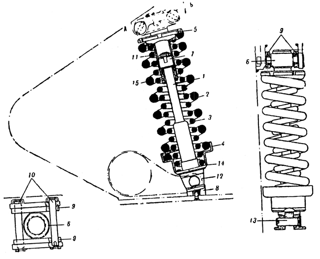
Plate 47 - Leading spring
1. Rod
2. External spring
3. Internal spring
4. Seating of external spring
5. Adjusting assembly
6. Adjusting nut
7. Nut
8. Buffer pad
9. Spigot carriers
10. Pins
11. Check nut
12. Spring
13. Pin
14. Guide ring
15. Guide bush
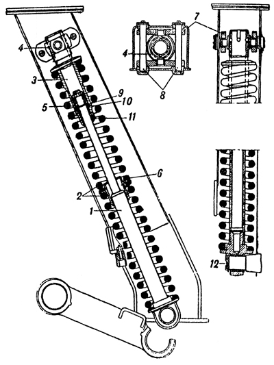
Plate 48 - 2nd, 3rd, 4th and 5th Springs
1. Rod
2. Springs
3. Adjusting assembly
4. Adjusting nut
5. Nut of rod
6. Spring guide bush
7. Spigot carriers
8. Pins of spigot carriers
9. Washer
10. Rings
11. Guide bush
12. Cap
Maintenance of the Suspension - Track Adjustment This is carried out in the following way :- The locking bolt of the axis of the crank is unscrewed to 12 to 15 mm. The nut is turned until the teeth of the crank and the bracket are no longer meshing. The unscrewing of the locks and nuts is carried out from the driving compartment. The nut is unscrewed by a special spanner.
In tanks with wireless sets it is necessary before adjusting the right hand track to turn the receiver lamp bracket through 90°. The key spanner unscrews the armoured plug in the nose plate of the hull. With the same key spanner turning the worm of the track adjusting mechanism, turn the crank in the necessary direction. When the tracks are normally adjusted there should be no flap and the middle part of the tracks should rest on top of the bogie wheels. After adjusting the tracks it is necessary to tighten the nut in the driving compartment, and replace the locking bolt. It is necessary to pay attention to see that the teeth of the crank are in mesh with the teeth of the bracket. If this is not so the axle of the crank is apt to break.
Fitting Tracks to the Tank
The tracks should be laid out in front of the tank. If both tracks have to be put on then it is necessary to draw the tank over the tracks by means of another tank or a tractor. On the other hand, if only one track has to be put on the tank can move under its own power. The tank should be moved over the tracks so that the last bogie wheel is resting on the one but last track link. It is also possible to position the tank over the tracks by lifting up one side of the hull with a jack. The crank of the track adjusting mechanism should be turned to the extreme rear position.
Join the front track link to the sprocket wheel by means of a steel cable. The cable should bc connected to two hinges of the track pin, at one end while the other end should be connected to a hinge pin resting between the two discs of the sprocket wheel.
The cable should then be wound round the sprocket wheel as though it were a capstan by engaging reverse gear a little bit at a time. The track should be pulled by the cable until the front track link reaches the sprocket wheel. Then disconnect the sprocket wheel by engaging 1st gear. Bring the upper run of the track into mesh with the sprocket with a crowbar. Pull the track with the sprocket by engaging reverse gear. Connect the track links with a track pin closing them up with the special device (Plate 49). Finally tension the track.
It is possible to fit one track without using a cable. Drive the tank so that the rear bogie rests on the track link 12th or 13th from the rear. Lever the track from the rear bogie by means of a baulk of timber and bring it into mesh with the sprocket by means of a crowbar. Drive the tank in 1st gear at a low engine speed over the track supporting the upper run of the track with a crowbar. Move the tank until the leading bogie rests on the second from front track link. Join the track links under the idler wheel by using the special device (Plate 49). Finally tension the track.
Plate 49 - Connecting the track by means of the special device
Chapter V. ELECTRICAL EQUIPMENT OF THE TANK
(Please note: due to the large number of cryillic characters in this section, I have used the closest Latin characters to make converting this section easier)
The electrical equipment of the tank consists of:
1. Generator and four accumulators.
2. Starter motor, turret traversing motor, electric fan, interior and exterior lighting, horn, wireless set and intercommunication system.
3. Driver's switch panel, turret switch panel, rotary base junction and earth switch.
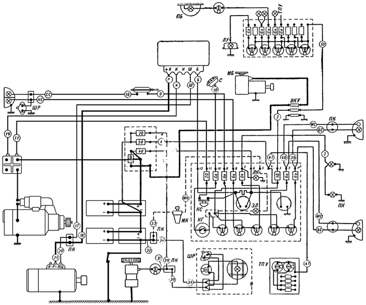
Plate 50 - Electrical Layout Of Tank
- Turret traverse motor - Horn - Transfer box - Horn button - Starter button - Green lamp - Oil cock - Plug-in rosette - Lamp illuminating clinometer - Turret roof - Lamp illuminating panel
(The strength of the current is indicated on the fuses. The figure in circles on the leads indicate the number of the lead. The number on leads from the turret panel have terminal numbers except Nos. 39, 40, 41. If each end of a lead has a different designation then both designations will be in the circle).
The electrical system of the tank consists of two circuits, one of 24V for the starter and turret traverse motor and the other 12 V for the remaining components.
The Generator 4563/A and the Voltage Regulator PPT 4576/A
The generator consists of a 24V shunt dynamo. The generator is mounted on the right side of the engine and is fastened by two securing bands. It is driven by the engine through a slipping clutch. The maximum capacity of the generator is 1 kilowatt.
The accumulators begin to be charged when the crankshaft reaches a speed of 600-650 rpm.
On the body of the generator there are three terminals "+R" , "K-p" and "+h". (ed: note these figures in quotes are barely legible and may be incorrect) "+R" is the positive terminal.
The generator works simultaneously with the voltage regulator which is mounted in the left instrument panel.
The voltage regulator consists of three controls: the cut-out, current limiter and voltage regulator.
The cut-out has the following purposes:
1. To engage the generator automatically when owing to increasing revs, its voltage becomes higher than that of the accumulators (25 to 27 volts).
2. For the automatic disengagement of the generator when its voltage is less than the voltage of the accumulators.
The voltage regulator maintains the voltage of the generator constant in spite of the changing engine revs. The constant current depends on the load. with loads of 30 Amps the voltage is 25 V. and travelling on the level at is 30-32V.
The current limiter limits the current from the generator to within 38-42 amps.
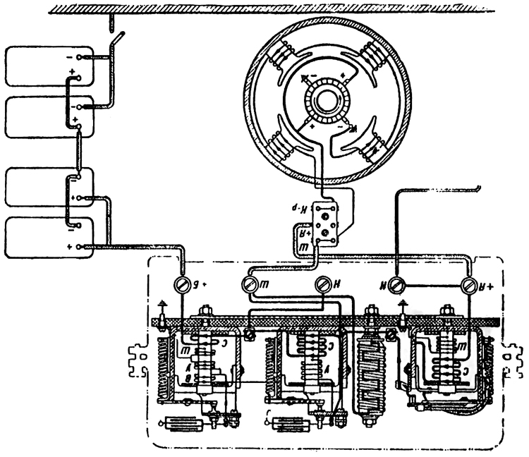
Plate 51 - Lay-out of coils of Voltage Regulator PPT 4576/A
The connection between the generator and the voltage regulator (Plate 51 ) From the terminal "+R" of the generator, the current travels to the lower terminal of the junction box on the right engine block and thence to the terminal "+R" of the voltage regulator. From the voltage regulator the current goes from the terminal "W" to the upper terminal "W" of the generator. From the terminal "5" of the voltage regulator the current travels to the terminal No.12 of the driver's switch panel, the ammeter and through terminal No. 6 across the fuse-box and fuse (4Oa) into the accumulator.
INSTRUCTIONS F0R REMOVING THE ACCOMULATORS.
1. Switch off the earth switch.
2. Remove the ammunition stored in the engine bulkhead.
3. Open the doors of the engine bulkhead.
4. Unscrew the negative terminal of the right front accumulator. Disconnect the bridge connecting the right and left group of accumulators. Disconnect the terminals of the left front accumulators.
5. Unscrew the nuts and remove the clamp holding the front accumulators.
6. Remove the front accumulators and take out the central securing board of the baskets of the front and rear accumulators.
7. Remove the rear accumulators.
To replace the accumulators the reverse order applies.
To connect the earth switch it is necessary to strike its head with the palm of the hand and press the knob at the side of the switch.
CT- 700 STARTER
The starter is mounted on a special platform on the gearbox with its starting relay to the right.
It is a 24 volt starter motor of 15 h.p. and consists of the following main parts: electric motor, control coupling, control relay, and starting relay.
The principal part of the starter is the series motor.
The control coupling slides on the splined shaft of the starter and consists of the starter gear and a multiplate clutch. A double shouldered forked lever moving on a shaft causes the coupling to be moved horizontally along the shaft thus engaging the toothed ring on the flywheel with the starter gear. For disengaging the coupling a return spring is provided on the shaft of the lever.
The action of the sliding coupling is as follows: by rotating the armature, the coupling transmits from the shaft to the starter gear and beyond to the toothed ring of the flywheel then the engine picks up and begins to turn at a greater number of revs than the starter motor, the sliding coupling disengages leaving the armature to revolve on its own. This protects the starter from damage.
The control relay PCT-334 is fixed to the starter. It has the following tasks :
1. To engage the starter with the toothed ring
2. When the gear is in mesh with the starter ring, to transmit current to the motor
The starting relay of the starter PC-371 and PC-400 serves to transmit the current to the starter when the button is pressed and to cut-out automatically the current after the engine is started. The starting relay consists of a powerful electromagnet and a contact system.
Testing the conditions of the accumulators
On connecting the earth switch the voltmeter should read 24-25 volts. A smaller voltage evidences a discharge.
When the accumulators are properly charged the charging unit should be 14-16 amps. When the engine is running at 900 rpm or more. With discharged batteries the current reaches 30 amps. The accumulators must be charged if the current reaches 20-22 amps.
The condition of the accumulators can be tested on the voltmeter by turning the engine round for three to five seconds without fuel by means of the starter.
With correct and charged accumulators the voltage must not be less than 17-18 volts. If less, then it is clear that there is either a fault or the accumulators are discharging.
With a cold engine in winter it is necessary to test the accumulators in this way since a fall in voltage is considerably greater with faulty and discharged accumulators.
The earth switch comprises a switch across the negative poles of the batteries which connects to the hull of the tank. It is situated on the right side of the tank at the right side of the wireless operator.
Installing the Starter in the Tank
The starter is mounted on the bracket 4 on the gearbox.
When installing the starter it is necessary to leave a clearance between the end of the gearwheel and the stater ring of 4 to 4.5 mm.
This clearance should be measured with a feeler gauge. The starter should be adjusted for height so that the clearance between the teeth of the gear wheel and the starter ring is 0.6-0.3 mm. This clearance is adjusted by the packing washers 5 between the bracket and the gearbox.
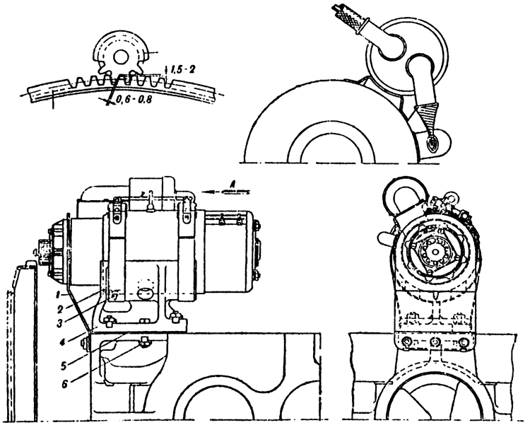
Plate 52 - Starter CT-700
1. Supporting bracket
2. Securing strap
3. Assembly pin
4. Bracket
5. Packing
6. Fitted bolt
Maintenance of the starter
1. Inspect the commutator and brushes once a month.
2. After every 50 working hours, remove the front cap of the starting relay and examine the contacts.
Lubrication
Every 12-15 engine working hours the lubricator at the side of the control should be filled with 15 to 20 drops of "Avia" oil and, having removed the cap of the bearing at the side of the commutator, pack the bearing with grease (Konstalin or Solidol).
DRIVER'S SWITCH PANEL
This panel is situated at the left of the driver and contains the ammeter and voltmeter. The general arrangement of the panel is shown in Plate 50.
The front headlight serves to illuminate the road at night and has two lamps one of greater brilliance than the other. The brighter light is marked (something I can't make out). The smaller lamp is operated by the switch marked "M CneT"
The tail light has two lamps one behind a blue glass and one behind a red glass. The upper blue light is operated on application of the brakes which causes the contacts of the "Stop" switch to be closed.
The Horn rø 4702 is of the vibrator type.
The electric fan MB12 is for ventilation of the fighting compartment.
Inspection lamp is mounted in the right front corner of the fighting compartment and can be used for illuminating the fighting compartment. It is portable and can be used when the earth is switched off.
Current supply panel for wireless and intercom is situated inside the glacis plate at the left of the wireless operator. It is connected to the terminal 4 on the main switch panel.
ELECTRICAL EQUIPMENT OF THE TURRET
The rotary base junction (BKy) is situated on the floor of the tank in the middle of the fighting compartment.
Inside the rotary base junction there is a system of insulated rings - three high tension and six low tension. The rings rotate with the turret and around them there are brushes which are fixed to the body of the rotary base junction.
Leads going to the tank are fixed to the bushes, and leads going to the turret from the rings. Through the lower No.1 ring the earth of the turret is connected, to the earth of the tank. Through the middle ring No. 2 +12V is transmitted to the turret, and through the upper ring No. 3 +24 volts is transmitted to the turret. The low tension rings are used for the intercom.
Turret traversing mechanism (Mb-20) has a capacity of 1350 watts, the maximum number of (something) per minute on the voltage 20V. The motor is controlled by the traversing handwheel and rheostat mounted on the motor. By turning the handwheel to the right, the turret is traversed to the right and by turning the handwheel to the left, the turret is traversed to the left.
The handwheel is locked automatically in the neutral position by the knob.
The rheostat handwheel has three positions at each side corresponding to three speeds. When using the motor the third or highest speed must always be used, as prolonged use of the rheostat causes it to overheat and burn.
PARTICULARS OF THE ELECTRIC EQUIPMENT OF THE TANK
1. It is necessary to dis-coru1oct the earth system then the engine is working otherwise the 12 volt components will burn.
2. By disconnecting the earth switch and switching on any component (except the inspection lamp) the voltmeter will indicate a voltage of 12 V.
3. The ammeter indicates the effective charging current of both groups of batteries only then the load is switched on.
4. On disconnecting the earth switch and connecting the traversing motor all the 12 volt users will work, supplied with current from the left group of batteries (except the inspection lamp).
BASIC RULES FOR THE ELECTRIC EQUIPMENT
1. During maintenance, disconnect the earth switch.
2. Then working in the Transmission compartment, the earth switch must be on.
3. The terminal nuts on the batteries should be kept firmly screwed down and oxidisation should not be allowed to form.
Table of Faults in Electrical Circuit of Tank
Fault Cause Means of Correcting Fault
1. Absence of current on the instrument panel, horn does not work, headlights and lamp not working but the voltmeter shows a voltage and starter works. Earth switched on a) Fuse No. 50 in the fuse box burnt out.
b) Loose connection between the fuse box and terminal 4 on the panel.
a) Replace
b) Test terminal nuts, replace lead
2. On pressing the starter button, the starting relay works, and the starter is switched on but is not strong enough to turn the engine round. The voltage falls below 17V.
a) Discharged or faulty accumulators
b) Extremely cold accumulators (in winter)
c) Loose high tension lead from the accumulators to the fuse box and to the earth switch
a) Replace
b) Place the accumulators in a warm place
c) Tighten terminals
3. The starter works but the engine is not turned over. a) Starter clutch slipping a) Remove starter and hand over to artificer for adjusting the coupling
4. After the engine has started, the starter gear does not disengage. a) Short circuit starter relay coil (leaked to earth)
b) Sooting up of the contacts in the starting relay
c) Seizing up of the coupling control on the shaft of the starter
a) Replace the relay
b) Replace the relay
c) Remove the starter and hand over to artificer
In all cases of the starter not disengaging, quickly stop the engine and switch off earth switch.
5. The ammeter does not indicate the charging current. a) Fuse 40 in the fuse box burnt out
b) Breakage or slackening of the contacts in the circuit connecting generator, voltage regulator and fuse box
c) Generator is not charging a) Replace the fuse
b) Test the following terminals for tightness: generator junction box, "+R", "M" and "B" on the voltage regulator " " on the panel and the leads 12, 17, 18.
c) Remove and replace
Test the connections of leads 20 and 21 from the terminals on the generator Junction box. Connect them across the lamp tester to earth. At an engine speed of 600-700 rpm the lamp should burn brightly in the case of a faultless generator.
6. Voltmeter does not show a reading, the starter functions and the ammeter shows a current.
a) Voltmeter defective
b) The bridge connecting the panel to earth is disconnected
a) Call out the electrician for replacement
b) Tighten connections
7. The turret traversing motor not working.
a) Fuse 200 in the fuse box burnt out
b) Terminals loose
c) Rotary base Junction disconnected or its brushes connecting poorly
d) Faulty motor
a) Replace
b) Test and tighten
c) Test and correct faults
d) Remove engine and hand over for repair
Chapter VI. GENERAL CONSTRUCTION AND EMPLOYMENT OF THE WIRELESS SET 9-P
(Please note: due to the large number of cryillic characters in this section, I have used the closest Latin characters to make converting this section easier)
General Description (Plate 54)
The purpose of the wireless set 9-P is for maintaining radio telephonic communication between the tank section and the separate tanks.
The rod aerial is 4 metres high.
The frequency of the transmitter is 4050 to 5625 kg.cy (??Hz??) (74 to 53.3 meters).
The range of the set is 18 km on the move and 25 km when stationary.
The Wireless set is designed to work with the intercom sets Tny 3 and Tny 4 BNC. The current supply for the set comes from the 12V circuit and the current supply for the intercom from the transformer -10.
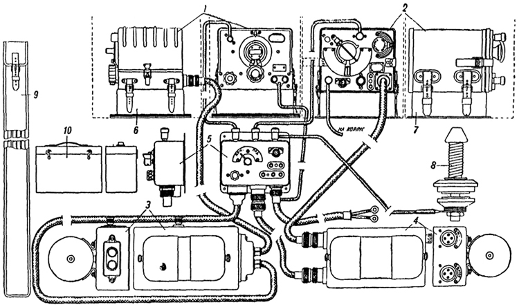
Plate 54 - Wireless installation 9-P
1. Receiver
2. Transmitter
3. PYH-10 Transformer with filter
4. PYH-30 Transformer with filter
5. Panel 6. Shock-absorbing pad of receiver
7. Shock-absorbing pad for 'transformer
8. Aerial holder
9. Case for rod aerial
10. Spares box.
Main Parts of Wireless Set (Plate 55)
1. Transmitter with shock-absorbing pad.
2. Receiver with shock-absorbing pad.
3. Transformer PyH-30 with filter.
4. Transformer PyH-10 with filter and two cables leading to panels and to receiver.
5. Control panel with feed cable (connecting the 12V circuit) and with telephonic flex (to receiver).
6. Headset with accessories (telephones, throat microphone, flex with forked plug}.
7. Cable connecting the feed plug of the transmitter to the left hand plug of the transformer PyH-30.
8. Cable connecting the middle plug of the panel to the right plug of the transformer PyH-30.
9. Aerial assembly consisting principally of a shock absorber and four equal lengths of rod.
10. Box of spare parts.
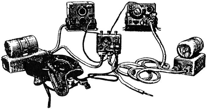
Plate 55 - Wireless Set 9-P
Inspection, Testing and Preparation of the Set
Before using the wireless set it must be tested and prepared.
The main parts of the wireless set as described above must be checked over separately and afterwards the set should be prepared in the following order :-
1. Fit the rod aerial and at the same time test its joints for tightness also test the terminals and leads to the transmitter and receiver for tightness and insulation.
2. Inspect the aerial insulator and clean off mud and dust.
3. Test for tightness the terminals of the leads from the aerial to the terminal "B" on thee panel and the connections between the terminals "A" and "Arl" on the panel of the receiver and transmitter.
4. Test and screw up the thick nut of the contact plugs of the current supply plugs.
5. Check the transformers paying special attention to the travel of the armature, cleanliness of the commutator and the size of the brushes. Replace worn brushes and rub new brushes.
6. Put on headset and see that telephones rest over the ears and that the throat microphone does not press too tightly against the throat.
7. Check the firmness of the transmitter, receiver and control panel. Test the transmitter indicator lamp.
8. Try out the aerial for receiving on three different frequencies.
9. Switch on the receiver and test it on the frequency. Then time (??tune??) the transmitter and reciever with the correct frequency.
TUNING THE TRANSMITTER
1. Raise the lever of the keeper on the transmitter handwheel and set the indicator needle over the ordered frequency then replace the keeper.
2. Set the switch on the panel to "nPII" (Transmit) than start the transformer PyH-30.
3. Set the tumbler switch on the panel to "BKH" and allow the transmitter to warm up for a minute.
4. Unscrew the keeper of the aerial tuning handwheel and by turning the handwheel find the maximum brilliance of the lamp.
5. Set the main switch to "nPM" (Receive) and than tune the receiver.
TUNING THE RECEIVER
1. The switch on the panel should be at "BKI" and the change-over switch to "nPM" (for this it is necessary to rotate the transformer PyH-10).
2. Turning the volume control knob with the inscription "TIIWIE-TPOM4C" (soft -loud) through the clock dial graduations up to its step (in half a minute it should be possible to hear a faint noise in the telephone).
3. Set the "HaCTPOHKA" (Tuning) knob of the reciever against the ordered frequency and obtain the boost volume for receiving the signals by slowly turning the knob.
4. By means of the knob "TIIWIE-TPOM4C" (soft -loud) establish the required volume.
5. After carrying out the above actions, the wireless set is fully prepared for use.
Basic Rules for Using the Wireless Set
1. Messages should be transmitted in short, clear and concise words without hurrying.
2. After speaking, quickly move the switch to "nPIIEM" (Receive).
3. Make sure that the throat microphone is correctly secured to the neck.
4. Do not have too great a volume (otherwise the wireless operator will be quickly exhausted and deafened).
5. After communication has ceased it essential to switch off the current supply by means of the tumbler switch.
INTERCOMMUNICATION SYSTEM
In T-34 tanks the internal communication system Tny-3 is fitted. In later models Tny-48IIC is fitted.
The purpose of the Tny-3 is for telephonic and signal communication between three of the crew and to link up the commander and wireless operator to the wireless set. It consists of the following instruments :-
1. Tank Commander's set.
2. Wireless operator's set.
}. Driver's set.
4. Three headsets type TrW.
5. Three microphones of type MA (with button).
6. Connecting cable.
7. Set of spares and instruments.
The telephone sets of the commander and driver have similar electrical circuits as well as being interchangeable.
Parts of the intercom set Tny-3
The commander's No.1 set provides. Intercommunication to all the crew and also can be used for receiving and transmitting through the wireless operator's set. On the front of this set is situated a button for calling the driver and wireless operator; here is also fixed red lamp for receiving and calling. On the left there are three plug sockets, the first with three holes for the microphone, the second with two holes is for the telephone and the third with one hole is for the additional microphone prong.
The No.2 set of the wireless operator provides intercom to all the crew and also to link the tank commander to the wireless. On the right it carries three plug sockets, one with three holes for the microphone, the second with one hole is for connecting the additional prong of the microphone and the third with holes for the telephone. Below it has a switch with three positions: "set to self" (PdIHOAI9I Ceb9), "Intercom" (BHyTPCIUdh C6936) and "set to No.1" (PdIINo IIR No.1). On the left there is a metal cover over a plate with six screws to which are secured the cables leading to the wireless set.
The No.3 set of the driver provides intercom to the members of the crew. The arrangement of No.3 set is exactly similar to No.1 set.
TO USE THE Tny-3
1. Switch on the current by means of the tumbler switch on the wireless set panel.
2. Clear signals can be obtained on the wireless operator's set by pressing the button while the switch is in any position, and also on the other sets by engaging and partly or fully disconnecting the telephones and microphones. The sending of signals is indicated by the red lamp on the calling set.
3. For speaking on the telephone, the microphone button must remain pressed.
4. For transmitting and receiving on the wireless set the wireless operator must move his switch to the position "set to self", and to connect the commander to the wireless set he must move the switch to the position "set to No.1". During the transmission over the wireless set, the button must remain pressed.
5. When conversation or communication on the wireless set is finished the button on the microphone must be released.
Chapter VII. MAINTENANCE
The tank must always be in complete fighting readiness. Reliable performance is only possible if the tank is properly maintained. Regular maintenance increases she life of the machine. Tank maintenance consists of :
1. Filling up with fuel, oil and water.
2. Periodical technical inspection.
3. Periodical lubrication.
4. Systematic checking of the adjustment of assemblies and of the controls.
FILLING UP
The fuel tanks should be filled with DT Diesel fuel or "gasoil" mark "3" through a double thickness of silk cloth. If a silk cloth is not available then it is possible to use a flannel with the nap upwards. The funnel must have a mesh filter (mesh size not less than No. 60).
The fuel should be filled into four tanks - 150 litres into the front tanks and 80 litres into the rear tanks and up to the level of the middle ring marked on the filter. The quantity of fuel is measured by a dipstick.
Diesel fuel, summer grade, is suitable for use at temperatures not less than +5°C and winter grade for use at temperatures of less then +5°C. Winter fuel can be used in summer. At temperatures below - 20°C, tractor kerosine should be added to DT winter fuel in the following proportions:
from -20 to -30°G 10% kerosine
from -30 to -35°C 25% kerosine
from -35 to -50°C 70% kerosine
The fuel can be drained from the drain plugs underneath the tanks. To do this the end of a flexible tube should be screwed on to the threaded plug which should then be unscrewed from 2 to 3 turns.
Oil
The oil tanks are filled with "Avia" oil MK or MS or MZS through the mesh filter (mesh size not being less than No. 60). In winter at temperatures below -20°C it is recommended to fill up with MZS "Avia" oil. Of the oil tanks two of 57 litre capacity each, are filled up to 40 litres. The quantity of oil is measured by a dipstick. The minimum permissible quantity of oil in the tanks is 20 litres.
The oil is drained through plugs situated in the base of the tanks. In winter it is recommended to drain off the oil before long halts. In winter the oil should only be filled after the engine has been warmed with water (warmed to 80-90°C) filled into the tanks and 5-6 litres into the engine.
Water
The cooling system is filled with water through the mouth of the filler opening over the engine. Into the mouth of the opening is introduced a funnel with mesh filter. If the steam valve is opened the water can be poured in more quickly.
The system will take 95 litres of water and the level should come to about 2-3 mm. from the base of the filler mouth.
A tap is fitted to the water plug to drain the water. To do this the hand lever of the tap on the engine bulkhead should be turned to the vertical position.
To clear the pump of water it is necessary to turn the crank shaft round 2-3 turns.
In winter at temperatures lower than -20°C the cooling system should be filled either with anti-freeze or a mixture of glycerine, spirit and water. Anti-freeze Expands on heating and therefore the cooling system should be filled with 5-6 litres less than when filling with water.
Sometimes anti-freeze will not flow, as at -50°C it is transformed into a porous mass but this does not cause cracks in the system.
Anti-freeze is a costly product and care must be taken to prevent wastage.
TECHNICAL INSPECTION OF THE VEHICLE
External Inspection
1. Inspect the condition of the tracks, track pins and their keepers, (split pins). Each track should be hit with a hammer to reveal any cracks.
2. Check the track tension.
3. Test the joint between the idler crank arm and the hull for firmness.
4. Check the lubricator plugs of the suspension for tightness.
5. Inspect the brackets and fixtures of the entrenching tool, spare tracks, jettison tanks, tarpaulin and tool box.
Inspection of Engine and Transmission Compartment
1. Every accessible place should be cleaned with a rag.
2. See that there are no foreign bodies on the floor under the fan.
3. Check the fuel, oil and water systems for correct flow. Test the "durite" hoses for firmness. Sec that the fuel system is hermetically sealed under 0.2 - 0.3 m/m.
4. See what the clearance between the brake bands and drums is 1.5 - 2.0 mm. all round.
5. See that there is no leakage of oil from the gearbox.
6. Test the tie rods and split pins of the control linkages.
Inspection of the Fighting And Driving Compartment
1. Test the locking of the nut of the idler wheel nut.
2. See that the accessories are not on the floor under the control-rods.
3. Test the working of the driving controls and see that the ball and socket joints are not disconnected, that the levers are not resting on the floor and that the split pins are properly secured.
4. Test the pressure in the air bottles. The maximum pressure is 15O atm. The minimum pressure is 30 atm. in summer and 65 atm. in winter.
5. Check the position of the hand levers of the drain cock:- horizontal position - cock closed, vertical - open.
6. Check the position of the fuel change-over cock. The hand lever should be pointing downwards - all tanks switched off.
7. Test the quality of grease in the water pump pressure lubricator.
8. Inspect the earth switch.
9. Check the fire extinguisher.
10. Inspect the working parts of the electrical circuit for damage.
11. Test the horn and lights.
INSPECTION OF THE TANK AFTER EVERY 10 - 12 HOURS TRAVEL OR AFTER COVERING 250-300 KM
What to Inspect What to do Method
Fuel Distributor cock Inspect and clean the mesh filter of the fuel distributor cock. To clean the filter unscrew the plug in the body of the cock and remove filter. Clean the filter in "gasoil" or petrol and afterwards blow out with air.
Oil and water radiators (and after travel through dust in summer) Inspect and when necessary clean the cooling surfaces from oil and dust. When possible it is recommended to clean the grooves of the radiators with compressed air.
Air cleaner (in summer) Remove, take down, clean and replace. Remove the cover of the air cleaner in one piece with its sections and wire-wool, clean the wire-wool in kerosine, place the cover and wire-wool in an oil bath so that the wire-wool absorbs the oil, remove is and allow the superfluous oil to drip off. Change the oil in the air cleaner oil bath.
Engine Clutch Test the engagement of the clutch and tightness of the control linkage. The travel of the presser plate should be 6-7 mm. If the travel of the presser plate is less than 6 mm the adjustment described in Chapter III should be carried out.
INSPECTION OF THE TANK AFTER EVERY 25 - 30 HOURS TRAVEL OR AFTER COVERING 500-600 KM
(IN ADDITION TO INSPECTION AFTER 10-12 HOURS)
What to Inspect What to do Method
Engine fuel and oil systems Inspect the oil and fuel leads. The hoses should be without cracks, twists, or kinks.
Engine fuel injection pump Inspect the fixture of the fuel injection pump on the crankcase.
Filters of the drain plugs of the oil tanks Inspect and clean the mesh filters of the radiator tanks Clean with "Gasoil"
Air cleaner (winter) Remove, take down, clean and replace. Remove the cover of the air cleaner in one piece with its sections and wire-wool, clean the wire-wool in kerosine, place the cover and wire-wool in an oil bath so that the wire-wool absorbs the oil, remove is and allow the superfluous oil to drip off. Change the oil in the air cleaner oil bath.
Tachometer and speedometer cables Inspect the attachment of the ends of the cables and the cable themselves.
Engine fuel filter Remove, take down, clean and replace according to instructions issued for maintenance of the engine lubrication system.
Oil filter Remove, take down, clean and replace according to instructions issued for maintenance of the engine lubrication system.
Engine clutch Check that the flywheel is seated firmly on the crankshaft. For this test the fan must be gripped by hand and rocked to and fro. There should be no play.
INSPECTION OF THE TANK AFTER EVERY 50 HOURS TRAVEL OR AFTER COVERING 1000 KM
(IN ADDITION TO INSPECTION AFTER 25-30 HOURS)
What to Inspect What to do Method
Final Drive Check the assembly locking spindles of the driven gear (by adjusting the conical bearing). If the play (looseness) of the assembly locking spindles is more than 0.15 mm, tighten the nut accordingly. Then slacken the nut 1/6 of a turn and fix split pin. To test the tightness of the assembly locking spindles it is necessary to disconnect the track and remove the sprocket wheel cap.
Assembly locking spindles of suspension arms. Check the tension of assembly locking spindles of the suspension arm. It is necessary to unscrew the cap on the ends of the suspension shaft (on one side of the tank). Tighten the nuts of the assembly locking spindles as required then slacken off 3/4 of a turn. For the suspension arms of four bogies it is necessary to tighten the nuts of the assembly locking spindle on both sides and slacken off 1/2 a turn.
Engine suspension Test the tension of the nuts securing the engine to the engine chassis. The nuts must be firmly tightened and fitted with split pins.
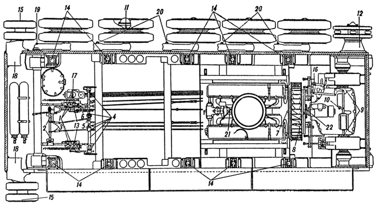
Plate 56 : Lubrication Chart
TABLE OF LUBRICATION
I. Lubricate every hour of engine running
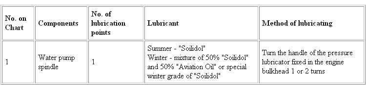
II. Lubricate after completion of 100 Km
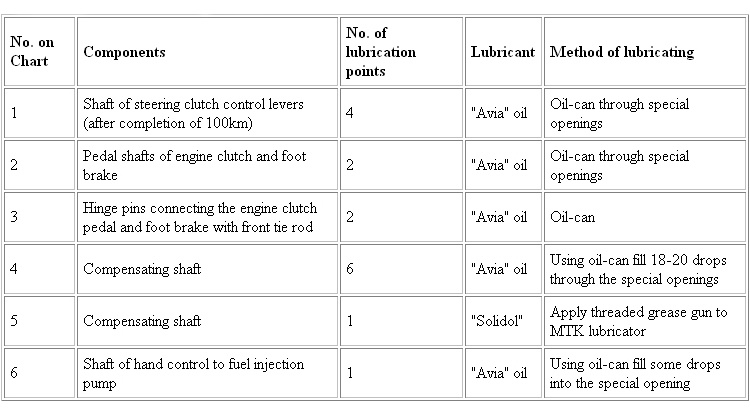
III. Lubricate at 250-300 Km or 10-12 engine running hours
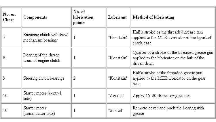
IV. Lubricate at 500 Km or 25 engine running hours
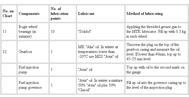
V. Lubricate at 1000 Km or 50 engine running hours
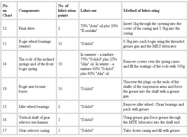
VI. Lubricate at 2000 Km or 100 engine running hours
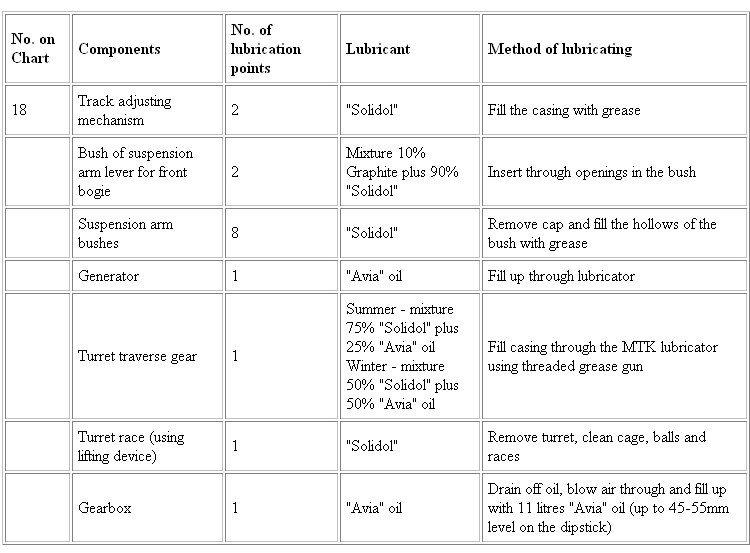
APPENDIX. MAIN DESIGN MODIFICATIONS IN T-34
Abolished:
(1) Inspection plug in upper collector tank of water radiator.
(2) Breathers and outlet cocks in oil tanks.
(3) Felt lining on wooden packing under the fuel and oil tanks.
(4) By-pass cock joining fuel feed tanks.
(5) Speedometer control.
(6) Horn.
(7) Lamps.
(8) Light illuminating clinometer.
Replacements:
(9) T-piece joining oil pipes is of welded construction of steel tubes instead of being cast.
(10) A combined air and steam valve instead of two separate valves for steam and air.
(11) The water pump spindle lubricator has a cast iron casing instead of being welded.
(12) One oil tank instead of there being on upper and lower tank there now being a total of two tanks instead of four.
(13) Cast sprocket wheel instead of forged.
(14) Cast bogie wheels instead of forged.
{15) Supporting studs for bogies instead of assembly lbcking spindles.
(16) Metal covers instead of rubber tyres.
(17) Two springs instead of four for the steering clutch control linkage.
(18) Prismatic drivers' sight instead of a periscopic (mirror) sight.
(19) The drivers' sight is replaced by the "nTnl" hand periscope.
(20) Turret vision arrangements replaced by prismatic sights.
Modifications:
(21) Securing of idler track adjusting mechanism.
(22) Design of the earth switch.
(23) Design of electrical instrument panel.
(24) Design of electrical panel in turret.
(25) Design of wireless supply panel.
Proposed:
(26) Two fuel tanks in the engine compartment for increasing the radius of action.