Slave to the Game
Online Gaming Community
ALL WORLD WARS
PERFORMANCE INVESTIGATION OF A JUMO 004 COMBUSTOR
by Robert C. Miller
RESEARCH MEMORANDUM
Air Materiel Command, Army Air Forces
PERFORMANCE INVESTIGATION of a JUMO 004 COMBUSTOR
By Robert C, Miller
Flight Propulsion Research Laboratory Cleveland, Ohio
NATIONAL ADVISORY COMMITTEE FOR AERONAUTICS
WASHINGTON
A German Jumo 004 combustor was investigated under conditions simulating zero-ram operation of a 24C jet-propulsion engine over ranges of altitude and engine speed to obtain the altitude oper¬ating limits and characteristics of the German combustor. The combustion efficiency, outlet-temperature distribution, and total- pressure drop were determined. A comparison of the performance of the combustor with 62-octane (AN-F-22) and JP-1 (AN-F-32) fuels was made.
The combustor was found to be altitude-limited at approxi¬mately 27,000 feet and 45,000 feet at low (5000 rpm) and high (11,000 rpm) simulated engine speeds, respectively, with 62-octane fuel and at altitudes of 22,000 feet and 47,000 feet, respectively, with JP-1 fuel. Local maximum and minimum values of combustor- temperature rise were about 30 percent higher and 10 percent lower, respectively, than the average combustor-temperature rise. Little or no resonant combustion was present at any of the operating conditions investigated. In the operating region approximately 15,000 feet below the altitude limit curve, combustion efficiency was 80 percent or greater; whereas combustion efficiencies approximately 5000 feet below the altitude operational limits varied from about 80 to 45 percent. The combustor total-pressure drop varied from about 2 to 6 percent of the inlet total pressure, with the lower percentage pressure drops occurring at the lower simulated engine speeds.
Experimental results also show that combustor-temperature rise for a given fuel-air ratio: (a) in general increased with increasing inlet-air total pressure; (b) increased with increasing inlet-air temperature; and (c) decreased with increasing inlet-air velocity. After 66 hours of combustion operation, no warping of the combustor was apparent.
As part of a program requested by the Air Materiel Command, Army Air Forces, to determine the effect of design on performance of turbojet-engine combustors, an investigation was made at the NACA Cleveland laboratory with one of six chambers of the same design that comprise the combustor section of the German manufac¬tured Jumo 004 turbojet engine.
Because combustor performance data are difficult to obtain from the complete engine assembly, the combustor was tested independently of the compressor and gas turbine. This simplified manner of testing makes it possible to study more conveniently the problems of combustion under various simulated engine operating conditions.
Altitude operational limits and combustion efficiencies were determined for a range of simulated altitudes and engine speeds using the operating conditions of a 24C turbojet engine inasmuch as this information on the Jumo 004 turbojet engine was unknown at the time of this investigation. In addition, the variation of combustion efficiency with fuel-air ratio, the combustor total- pressure drop, outlet-temperature distribution, and the effects of independently varying combustor inlet-air temperature, pressure, and velocity were investigated. These data were desired in order to evaluate partly the current state of development of combustion chambers for aircraft gas turbines and turbojet engines.
Combustor
A diagrammatic sketch of the Jumo 004 test setup showing the combustor and auxiliary ducting is shown in figure 1. Three quartz observation windows were installed in the combustor and adjacent ducting to permit axial and radial views of combustion. A series of photographs of the Jumo 004 combustor showing sequence of the assembly of the outer shell, the flame tube, the fuel- injection nozzle, and the liner are shown in figure 2(a). Several views of the flame tube are presented in figures 2(b) to 2(d). Figure 2 also shows the general construction of the combustor including the inlet-air swirl vanes (swirl, approximately 60°) and the respective locations of the fuel-injection nozzle and spark plug (figs. 2(c) and 2(b), respectively).
The liner and flame tube are constructed from 20-gage mild steel. Both are protected by an aluminum-oxide coating (refer¬ence 1) with the exception of the upstream half of the flame tube. The fuel-injection nozzle is a centrifugal, hollow-cone spray type (spray angle, 60°; delivery, 185 lb of AN-F-22 fuel/hr at 100 lb/sq in. pressure), which sprays the fuel upstream. A cut¬away assembly drawing of the combustor illustrating the general air-flow pattern is shown in figure 3.
Instrumentation
Temperature and pressure-measuring instruments were located at three sections, A, B, and C, as indicated in figure 4. The number and type of instruments at each section are presented in the following table:
Instrumentation section |
Number of instruments |
||
| Thermocouples | Total-pressure probs | Well static-pressure orofices | |
| Combustor inlet, A | 3 | 4 | 2 |
| Combustor outlet, B | 24 | 12 | 4 |
| Discharge, C | 6 | 0 | 0 |
The construction and installation details of the combustor instru¬mentation are, in general, the same as those of reference 2. The thermocouples and total-pressure probes were located at approxi¬mate centers of equal areas. The thermocouples were made of chromel-alumel wire and were connected to self-balancing poten¬tiometers. Fuel flow was measured with a calibrated rotameter and combustion-air flow was measured with a 12-inch variable- area orifice. Pressure measurements were taken by photographing banks of manometers.
Performance data supplied by the manufacturer of the 24C turbo¬jet engine were used to determine combustor-inlet and combustor-outlet conditions required to simulate zero-ram operation of the Jumo 004 combustor, inasmuch as this information on the Jumo 004 turbojet engine was not available at the time of this investigation. Air weight flow per unit area through the maximum cross-sectional area of the Jumo 004 combustor was fixed as equivalent to the air weight flow per unit area through the maximum cross-sectional area of the 24C combustor. The inlet-air conditions of total pressure, temperature, and weight flow and the required combustor-outlet gas temperatures as set up for the Jumo 004 combustor investigation are presented in figure 5 for simulated ranges of altitude (0 to 50,000 ft) and engine speed (4000 to 12,000 rpm).
In general, the ignition of the fuel-air mixture by the Jumo 004 spark plug was obtained at the following approximate conditions: (a) air flow, 0,60 pounds per second; (b) inlet total pressure, 29 inches mercury absolute; and (c) fuel flow, 35 pounds per hour. After ignition, all operating points were approached by- setting the inlet-air temperature, increasing the air flow to the desired value, and adjusting the fuel flow to give the required combustor-temperature rise. Inlet total pressure, in general, was initially higher than required and was reduced.
The altitude operational limits of the engine as imposed by the combustor were established by operating the combustor at inlet-air conditions simulating zero-ram operation over a range of altitudes and engine speeds. For each simulated altitude-engine speed condition, the fuel flow was varied through a wide range in an attempt to obtain the combustor-temperature rise required for engine operation at the simulated flight conditions. If the required temperature rise could be obtained, the simulated flight condition's were considered to be within the operable range of the engine; if the required temperature rise was not obtainable, the flight conditions were considered to be in the inoperable range.
Combustion efficiency (defined as the ratio of measured temperature rise to the theoretical temperature rise as obtained from reference 3) was determined for all operating points inves¬tigated. Data for the combustion efficiency at a given simulated engine speed and altitude were recorded only when the combustor- outlet temperature was set at the required value for this engine condition or not more than 20° F higher. All the runs were made using 62-octane gasoline (AW-F-22); however, altitude operational limits were also determined using JP-1 (M-F-32) fuel.
The sensitivity of the Jumo 004 combustor to variations in the inlet-air parameters of total pressure, temperature, and velocity was determined "by holding two of the parameters constant for any test and independently varying the other. In general for each set of combustor-inlet conditions, the fuel-air ratio was varied to the limits of combustion. The quantity presented as the inlet-air velocity was computed from the mass flow of air, the maximum cross- sectional area of the combustor, and the density of the air at the combustor inlet; inlet-air dynamic pressure was computed from the inlet velocity as just defined and the inlet density. This expres¬sion of inlet velocity and. dynamic pressure was used in order to facilitate comparison of this combustor with other turbojet-engine combustion chambers. Data were found to be reproducible within 5 percent.
Altitude Operational Limits
The altitude-operational-limit curve for AN-F-22 fuel is presented in figure 6 in a plot with altitude and engine speed as coordinates. This curve separates the region where the required combustor-outlet gas temperatures were obtainable from the region where the required combustor-outlet temperatures were not obtainable for the steady zero-ram operation of the turbojet •, engine. The altitude limits for the combustor were approximately 27,000 and 45,000 feet at simulated engine speeds of 5000 and 11,000 rpm, respectively. A tabulation of combustion efficiency at each operable point and three lines of constant combustion efficiency (70, 80, and 85 percent) obtained by interpolating between the data points are included in figure 6. The altitude operational limits determined for AW-F-32 fuel are presented in figure 7 with the altitude-operational-limit curve of figure 6 shown for comparison. The altitude limit was reached in this case at approximately 22,000 and 47,000 feet at simulated engine speeds of 5000 and 11,000 rpm, respectively.
Combustion Efficiency
The combustion-efficiency data presented in figure 6 show that the lines of constant combustion efficiency have the same general shape as the curve of the altitude operational limits; however, at the low engine speeds the spread between the lines shown is slightly larger than that at the high engine speeds. At operating points approximately 15,000 feet below the alti¬tude operational-limit curve, values of combustion efficiency of 80 percent or greater are indicated, whereas, at conditions 5000 feet "below the altitude-operational-limit curve, combustion efficiencies ranging from about 45 to 80 percent are shown.
Typical variations of combustion efficiency with fuel-air ratio are presented in figure 8 for two operating conditions (15,000 ft,. 6,000 rpm; and 35,000 ft, 11,000 rpm). Data for the same two operating points are presented in figure 9 to show the variation cf combustor-temperature rise with fuel-air ratio. In general, combustion efficiency decreased with fuel-air ratio (fig. 8) and combustor-temperature rise increased with fuel-air ratio (fig. 9). The decrease in combustion efficiency with fuel- air ratio was greater at altitudes approaching the operational limits and as a result a peak value of combustor-temperature rise was generally obtained as fuel-air ratio was increased at altitudes near the operational limits, as will be shown later.
Effect of Varying Inlet Parameters
The results of independently varying the inlet-air conditions to determine their effect on combustor-temperature rise are pre¬sented in figure 10. The following reference inlet-air conditions were used: total pressure, 13.9 inches of mercury absolute; tem¬perature, 39° F; and velocity, 202 feet per second. These condi¬tions simulate an engine speed of 7000 rpm and an altitude of 35,000 feet, which lies close to the altitude-operational-limit curve.
A plot of combustor-temperature rise against fuel-air ratio for inlet-air total pressures of 13.0 to 18.0 inches of mercury absolute is presented in figure 10(a). The general trend of the data shows that at a given fuel-air ratio the combustor-temperature rise increases with increasing inlet-air total pressure; however, the data at an inlet pressure of 13.9 inches of mercury disagree with this general trend. It is possible that this reversal in trend is within the limits of experimental accuracy because a relatively small temperature range is covered by the data and the operational characteristics at the reference operating conditions were poor. In previous work (for example, reference 4), it has been shown that at a given fuel-air ratio combustor-temperature rise increases with increasing pressure. The maximum combustor- temperature rise was obtained between fuel-air ratios of approxi¬mately 0.010 and 0.013 for all pressures.
The variation of combustor-temperature rise with fuel-air ratio is shown in figure 10(b) for inlet-air temperatures ranging from 0 to 190 F. In every case, Increasing inlet-air temperature resulted in an increased combustor-temperature rise. Maximum combustor-temperature rise was obtained in the range of fuel-air ratios from 0.012 to 0.018.
Combustor-temperature rise for inlet-air velocities of 164 to 227 feet per second was determined for a range of fuel-air ratios. As presented in figure 10(c), combustor-temperature rise decreased with increasing inlet-air velocity for any given constant fuel-air ratio. Maximum combustor-temperature rise was obtained in the range of fuel-air ratio from 0.012 to 0.013 for the range of inlet-air velocities shown in figure 10(c). A small trend toward increased optimum fuel-air ratio with decreased inlet-air velocity is noted; based on investigations of other combustors (reference 4, for example), it is probable that as inlet-air velocity further decreases the peak combustor-temperature rise will shift to higher fuel-air ratios.
Temperature Distribution
The temperature distribution at the combustor outlet (sec¬tion B) is shown for two operating points, 7000 rpm and 35,000 feet (fig. 11(a)) and 11,000 rpm and 35,000 feet (fig. 11(b)). These temperature distributions are typical for both 62-octane (AN-F-22) and JP-1 (AN-F-32) fuels in that temperatures measured near the outer wall and the center of the combustor-outlet section (sec¬tion B) were lower than temperatures recorded between these radial sections. This temperature pattern is probably a result of the method of cooling the outer shell with a portion of inlet air and by the mixing baffle at the downstream end of the .flame tube. (See fig. 3.) Local maximum and minimum values of combustor-temperature rise were about 30 percent higher and 10 percent lower, respec¬tively, than the average combustor-temperature rise for all points.
General Operating Characteristics.
When 62-octane fuel was used at altitudes above the operating limits, combustor-temperature rise increased continuously with an increase in fuel-air ratio until the flames were extinguished, but blow-out occurred before the required combustor-outlet temperature was reached. When JP-1 fuel was used, flickering burning and a maximum combustor-outlet temperature below that required was obtained with an increase in fuel-air ratio before blow-out occurred. For the altitude-limit runs with JP-1 fuel, it was found necessary to ignite the combustor with 62-octane fuel to obtain satisfactory ignition. Carbon formation was negligible with 62-octane gasoline. During the runs with JP-1 fuel, however, the spark plug required frequent cleaning and carbon deposits were evi¬dent in the upstream end of the flame tube. For both fuels an intensified flickering of the flames at the upstream end of the flame tube was apparent before blow-out, which was the only indica¬tion of resonance. Wo appreciable afterburning was at any time encountered from section B (combustor outlet) to section C (dis¬charge section). After 66 hours of combustion operation, no warp¬ing of the flame tube or liner was detected and the combustor was apparently in the same condition as when installed.
Pressure Drop
A combustor pressure-drop correlation is presented in fig¬ure 12 in terms of the ratio of combustor total-pressure drop to inlet dynamic pressure (Pa-b)/qA against inlet-to-outlet density ratio Pa/PB. The value of (Pa-b)/qa varied from about 10.5 at isothermal conditions (pa/pb = 1) to roughly 13.0 during combustion (pA/pb = 2.4), at which condition appreciable scatter of the data exists. The value of (Pa-b)/qa obtained during combustion corresponds to pressure drops of from 2 to 6 percent of the inlet-total pressure with the lower percentage drops occurring in the low engine-speed range.
From an investigation of the Jumo 004 combustor under condi¬tions of combustor inlet-air pressure, temperature and velocity simulating zero-ram operation of the 24C turbojet engine, the following results were obtained;
1. The operable range of the Jumo 004 combustor, as deter¬mined by its ability to produce the temperature rise required by the 24C turbojet reference engine, had maximum simulated altitudes of 27,000 and 4-5,000 feet at simulated engine speeds of 5000 and 11,000 rpm, respectively, with 62-octane fuel. Altitude opera¬tional limits with JP-1 fuel were 22,000 and 47,000 feet at simulated engine speeds of 5000 and 11,000 rpm, respectively.
2. In the operating region approximately 15,000 feet below the operational limits, the average combustion efficiency was 80 percent or greater. This efficiency varied from about 80 to 45 percent at altitudes approximately 5000 feet below the opera¬tional limits.
3. The maximum combustor-temperature rise was attained in the fuel-air-ratio range of 0.012 to 0.015 for most of the oper¬ating points tested near the altitude operational limit.
4. Local maximum and minimum values of combustor-temperature rise were about 30 percent higher and 10 percent lower, respec¬tively, than the average combustor-temperature rise for all points tested.
5. The combustor total-pressure drop varied from 2 to 6 per¬cent of the inlet total pressure, with the lower percentage pres¬sure drops occurring at the lower engine speeds.
6. Combustor-temperature rise for a given fuel-air ratio: (a) decreased with increasing inlet-air velocity; (b) increased with increasing inlet-air temperature; (c) in general increased with increasing inlet-air total pressure.
7. After 66 hours of combustion operation, no warping of the flame tube or liner was detected and the combustor was apparently in the same condition as when installed.
Flight Propulsion Research Laboratory,
National Advisory Committee for Aeronautics, Cleveland, Ohio.
Robert C. Miller, Mechanical Engineer.
Approved:
Walter T. Olson, Chemist.
Benjamin Pinkel, Physicist.
1. Anon.: Report on the Metallurgical Examination of a Combustion Chamber Taken from a Crashed German Me 262 Jet Propelled Aircraft. Paper No. E.C. 185. High Temperature Material Res. Comm., Nat. Phys. Lab., Ministry Aircraft Prod. (British) Jan. 1945.
2. Manganiello, Eugene J., and Bogart, Donald: Simulated Altitude Performance of Combustors for the Westinghouse 9.5 Jet Engine. I - 9.5A Combustor. NACA MR No. E6F28, Bur. Aero., 1946.
3. Turner, L. Richard; and Lord, Albert M.: Thermodynamic Charts for the Computation of Combustion and Mixture Temperatures at Constant Pressure. NACA TN No. 1086, 1946.
4. Childs, J. Howard, McCafferty, Richard J., and Surine, Oakley W. A Study of Combustion Performance in a Westinghouse 19-B Combustor. NACA MR No. E6H05, Bur. Aero., 1946.
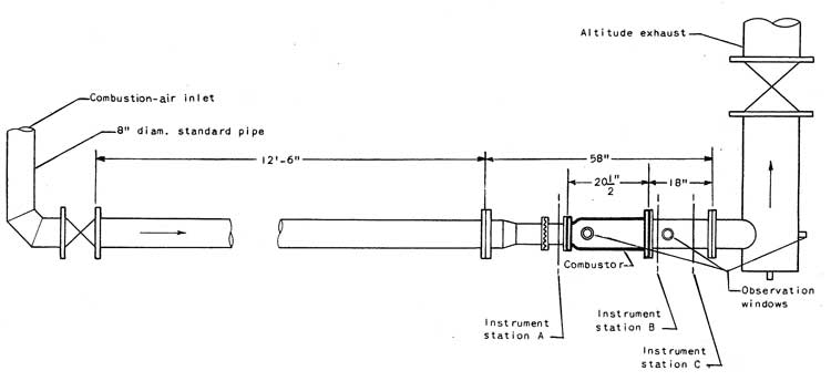
Figure I. - Diagrammatic sketch of Jumo 004 combustor and auxiliary ducting.
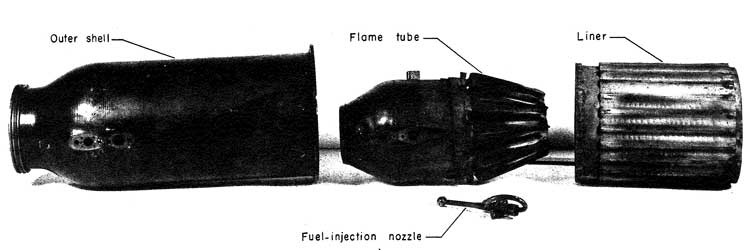
Figure 2. - Jumo 004 combustor. (a) Outer shell, flame tube, fuel-injection nozzle and liner sequence in assembly.
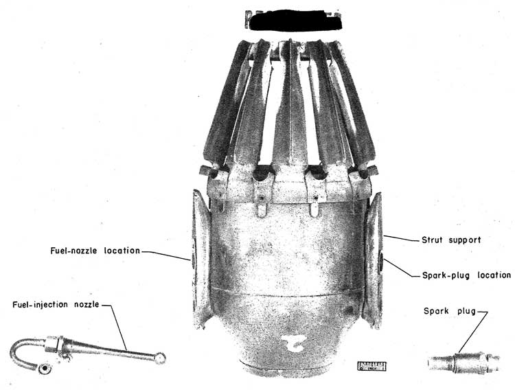
Figure 2. (Continued). Jumo 004 combustor.
(b) Side view of flame tube showing location of fueI-injection nozzle and spark plug.
Figure 2. (Continued). Jumo 004 combustor.
(c) Upstream end of flame tube showing inlet-air swirl vanes
Figure 2. (Concluded). Jumo 004 combustor.
d) Downstream end of flame tube.
Figure 3. - Assembly drawing of Jumo 004 combustor illustrating general air-flow pattern through combustor.
Figure 4. - Schematic drawing of Jumo 004 combustor and auxiliary ducting showing three instrumentation sections and location of thermocouples and pressure tubes.
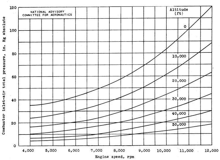
Figure 5. - Operating conditions used for Jumo 004.combustor.
(a) Variation of combustor inlet-air total pressure with simulated engine speed and altitude.
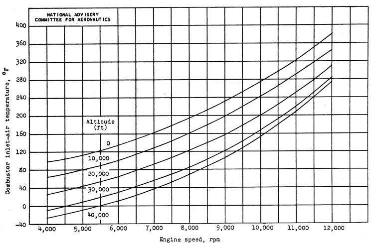
Figure 5. (Continued). Operating conditions used for Jumo 004.combustor.
(b) Variation of combustor inlet-air temperature with simulated engine speed and altitude.
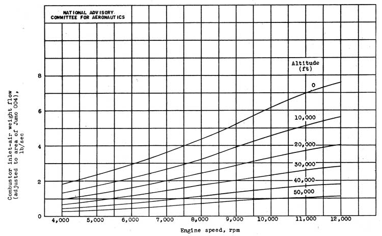
Figure 5. (Continued). Operating conditions used for Jumo 004.combustor.
(c) Variation of combustor inlet-air weight flow with simulated engine speed and altitude.
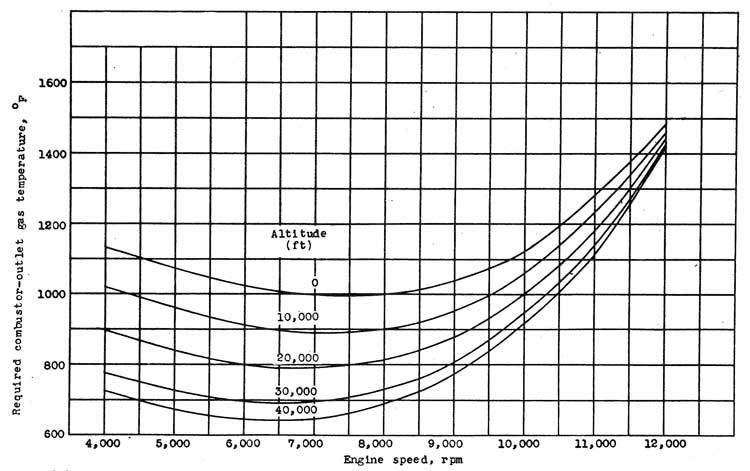
Figure 5. (Concluded). Operating conditions used for Jumo 004 combustor.
(d) Variation of required combustor-outlet gas temperature with simulated engine speed and altitude.
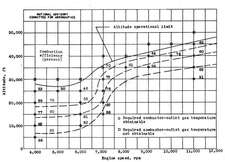
Figure 6. - Altitude operational limits and combustion efficiencies of Jumo 004 combustor uising 62-octane (AN-F-22) fuel. Numbers refer to combustion efficiencies.
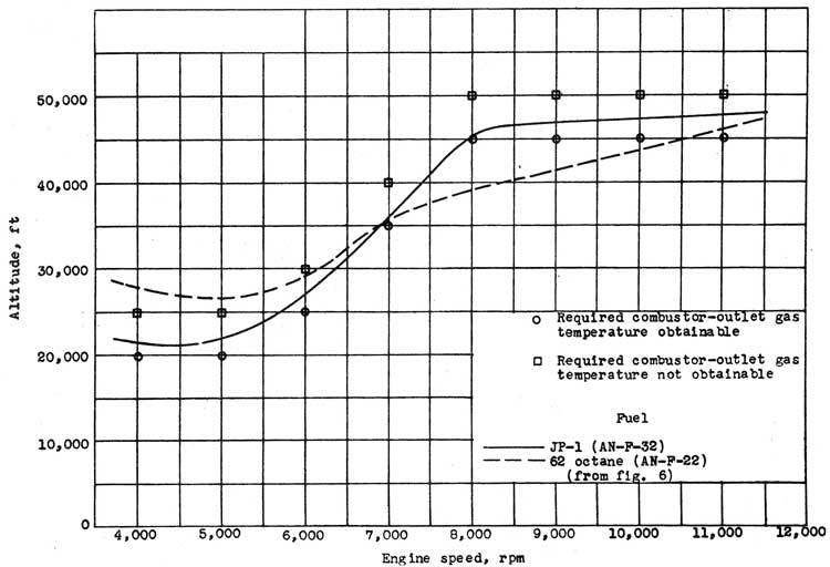
Figure 7. - Altitude operational limits of Jumo 004 combustor using JP-1 (AN-F-32) fuel.
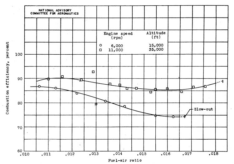
Figure 8. - Variation of combustion efficiency with fuel-air ratio for two simulated operating points. Jumo 004 combustor; fuel, 62 octane (AN-F-22).
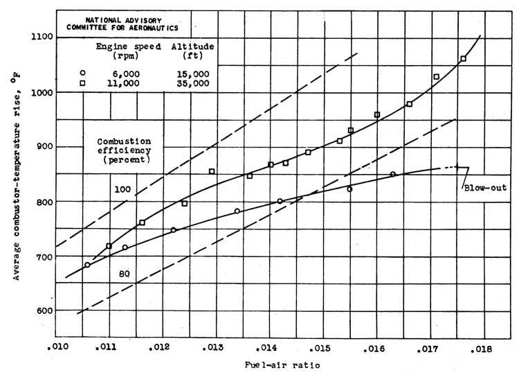
Figure 9, - Variation of average combustor-temperature rise with fuel-air ratio for two simulated operating points. Jumo 004 combustor fuel, 62 octane (AN-F-22).
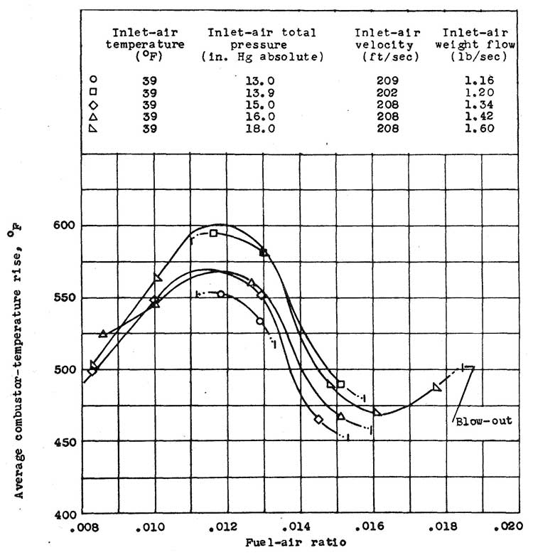
Figure 10. - Variation of average combustor-temperature rise with fuel-air ratio for several inlet-air parameters. Jumo 004 combustor; fuel, 62 octane (AN-F-22)
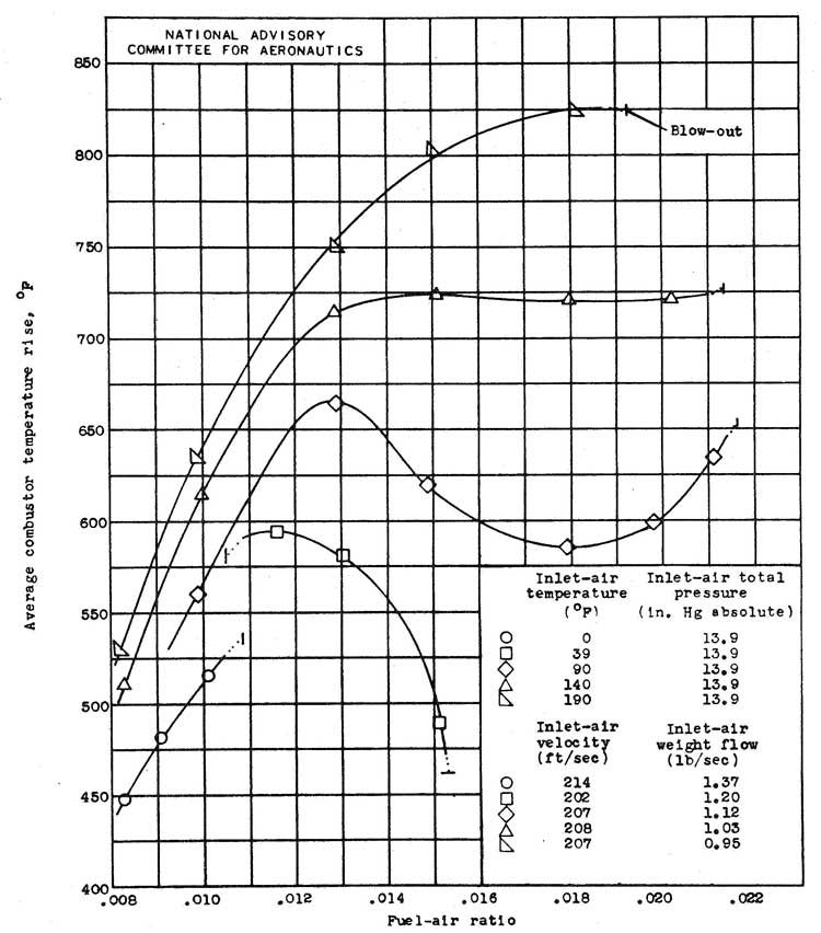
Figure 10. (Continued.) Variation of average combustor-temperature rise with fuel-air ratio for several Inlet-air parameters. Jumo 004 combustor; fuel, 62 octane (AN-P-22).
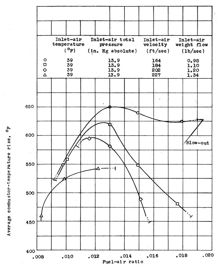
Figure 10. (Concluded.) Variation of average combustor-temperature rise with fuel-air ratio for several inlet-air parameters. Jumo 004 combustion fuel, 63 octane (AN-F-22).
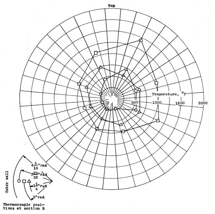
Figure 11. - Temperature distribution at combustor outlet (section B, looking upstream) Jumo 004 combustor; fuel, 62 octane (AN-F-22).
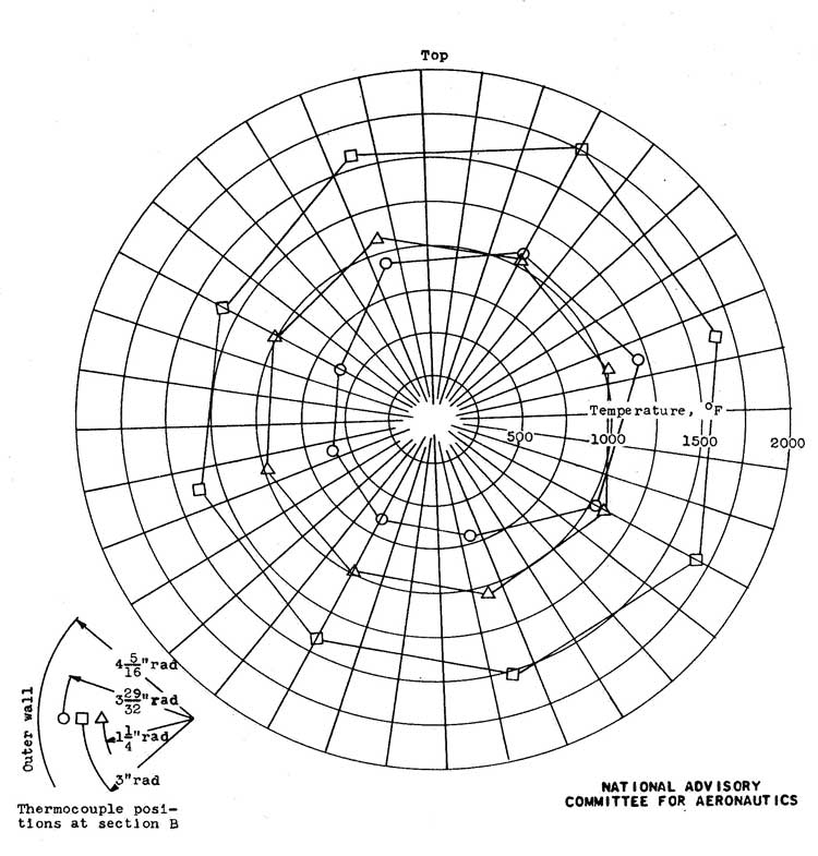
Figure 11. (Concluded.) Temperature distribution at combustor outlet (section B, looking upstream). Jumo 004 combustor; fuel, 62 octane (AN-F-22).
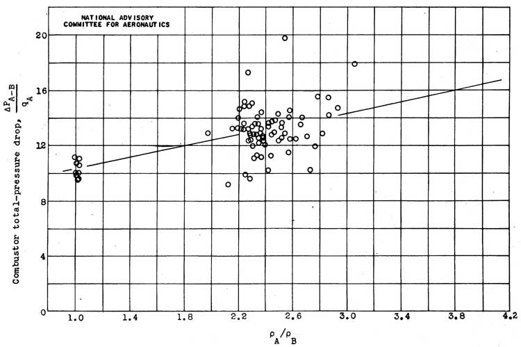
Figure 12. - Correlation of combustor total-pressure drop with inlet-to-outlet density ratio. Jumo 004 combustor.